Tag Archives: DSB

The BitX 20 & More

The BitX

20160618_120709
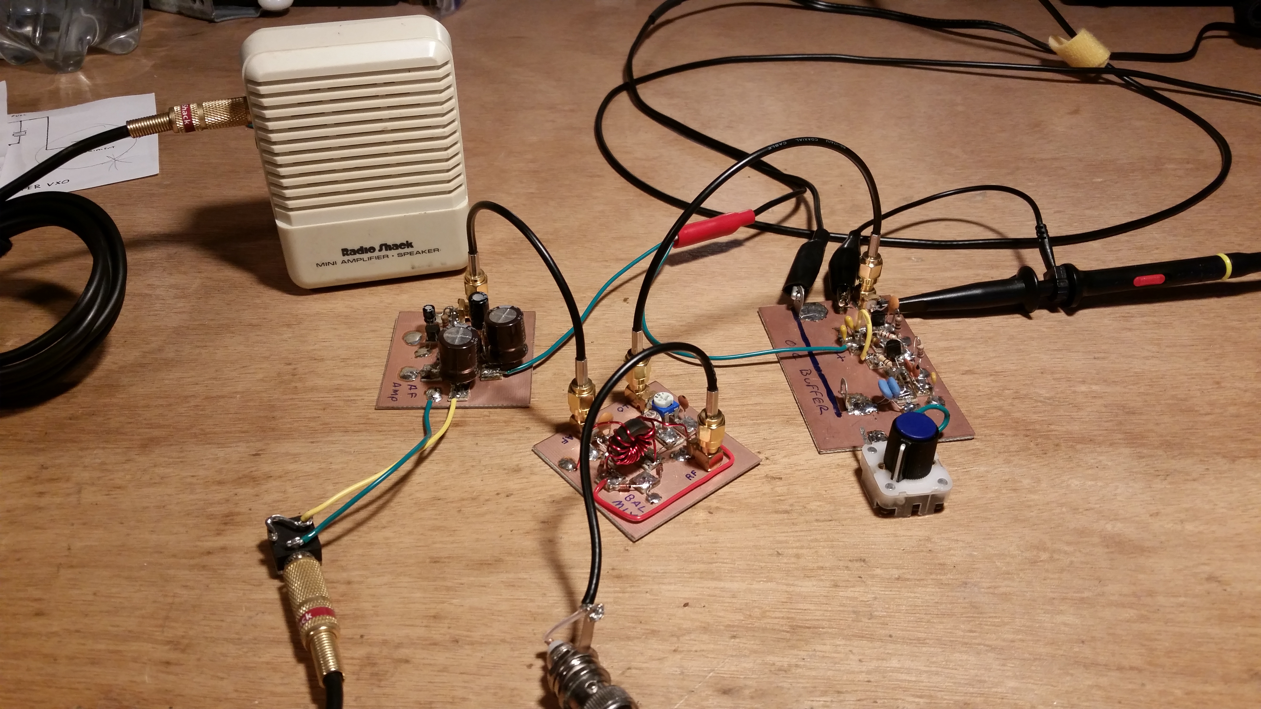
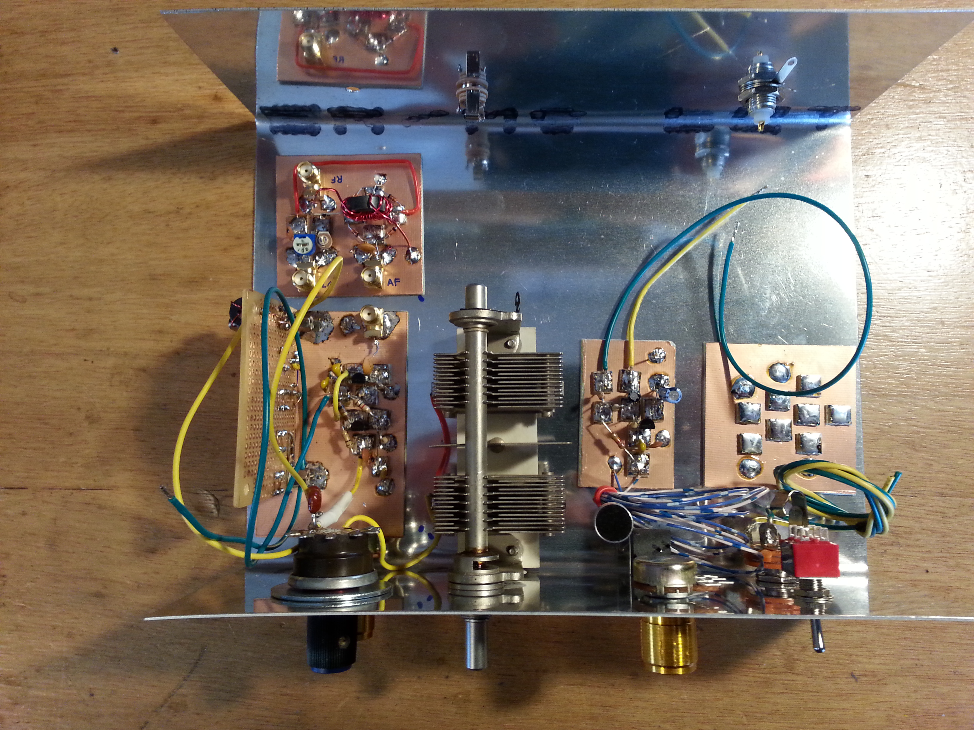
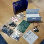
I was fortunate to recently have been gifted a BitX 20 kit by a friend and fellow VE. The kit came from QRPkits.com some time ago, I believe at least a year or so ago.

My intention was to build it for Field Day 2016. Sadly, while I was well on track to getting the radio built, 2 parts were missing from the kit. BS170 N-Channel MOSFETs to be specific. This put on the breaks for the final assembly and stopped me dead in my tracks with the finish line in sight.

20160624_193754
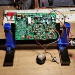
I have the parts waiting for me at Jameco will-call for Monday. Once I get them home, populating the remainder of the circuit board should take about an hour. Then its on to the initial tuning and getting the radio packaged up in its housing.

I will do a full project write-up in the Projects section soon, but for now just an update.

A Homebrew Signal Generator/Oscillator

20160622_084953
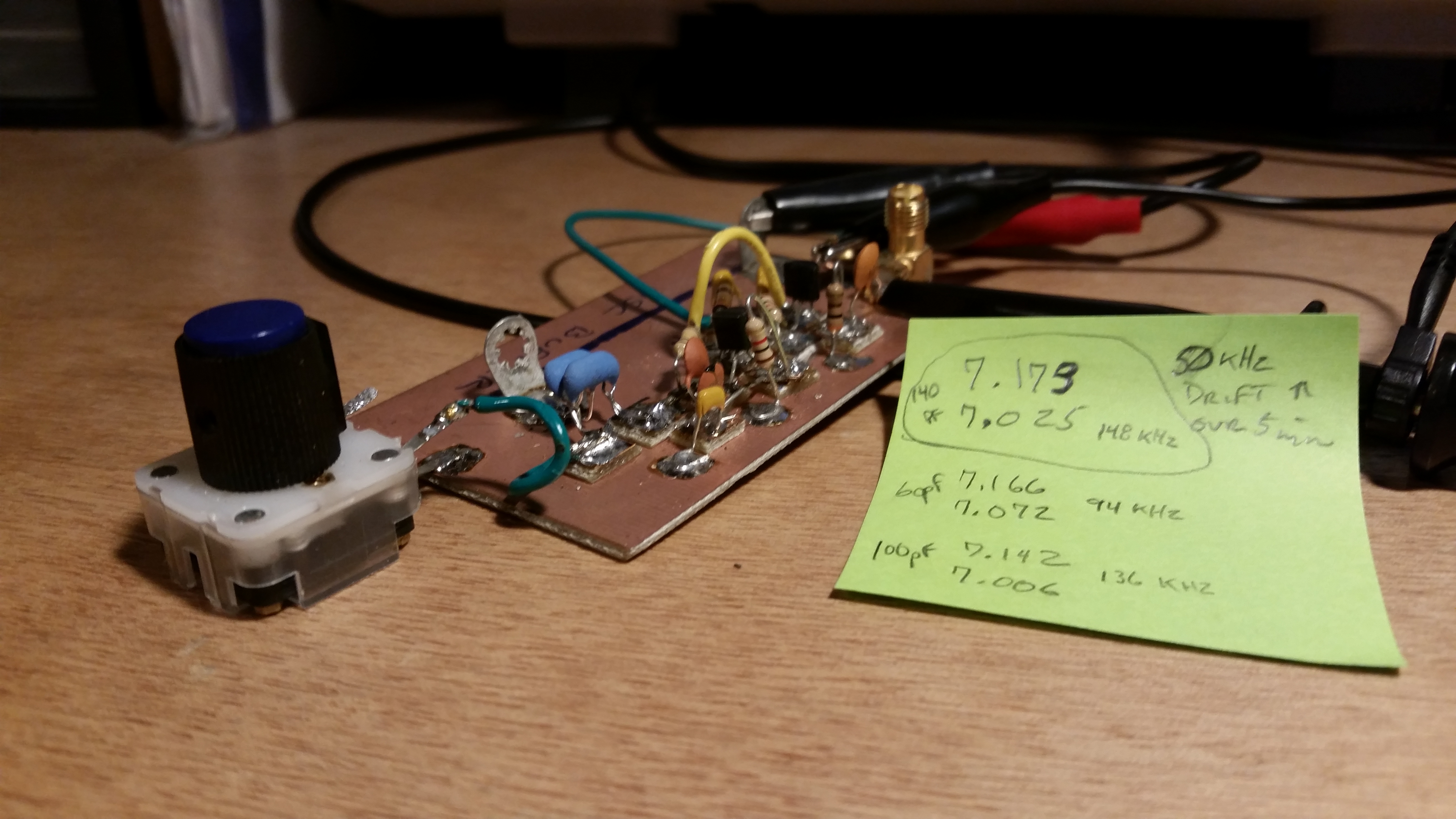
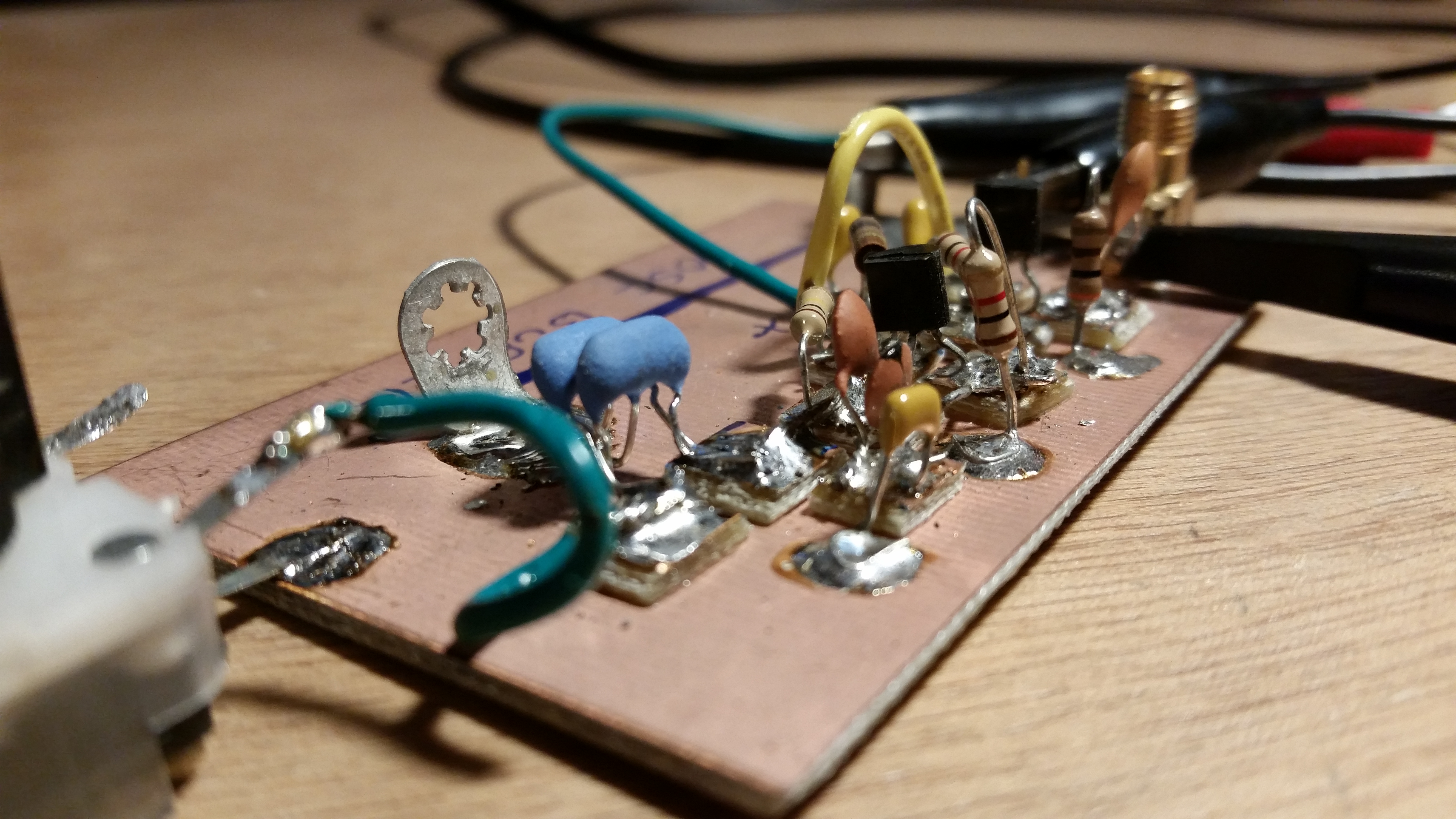
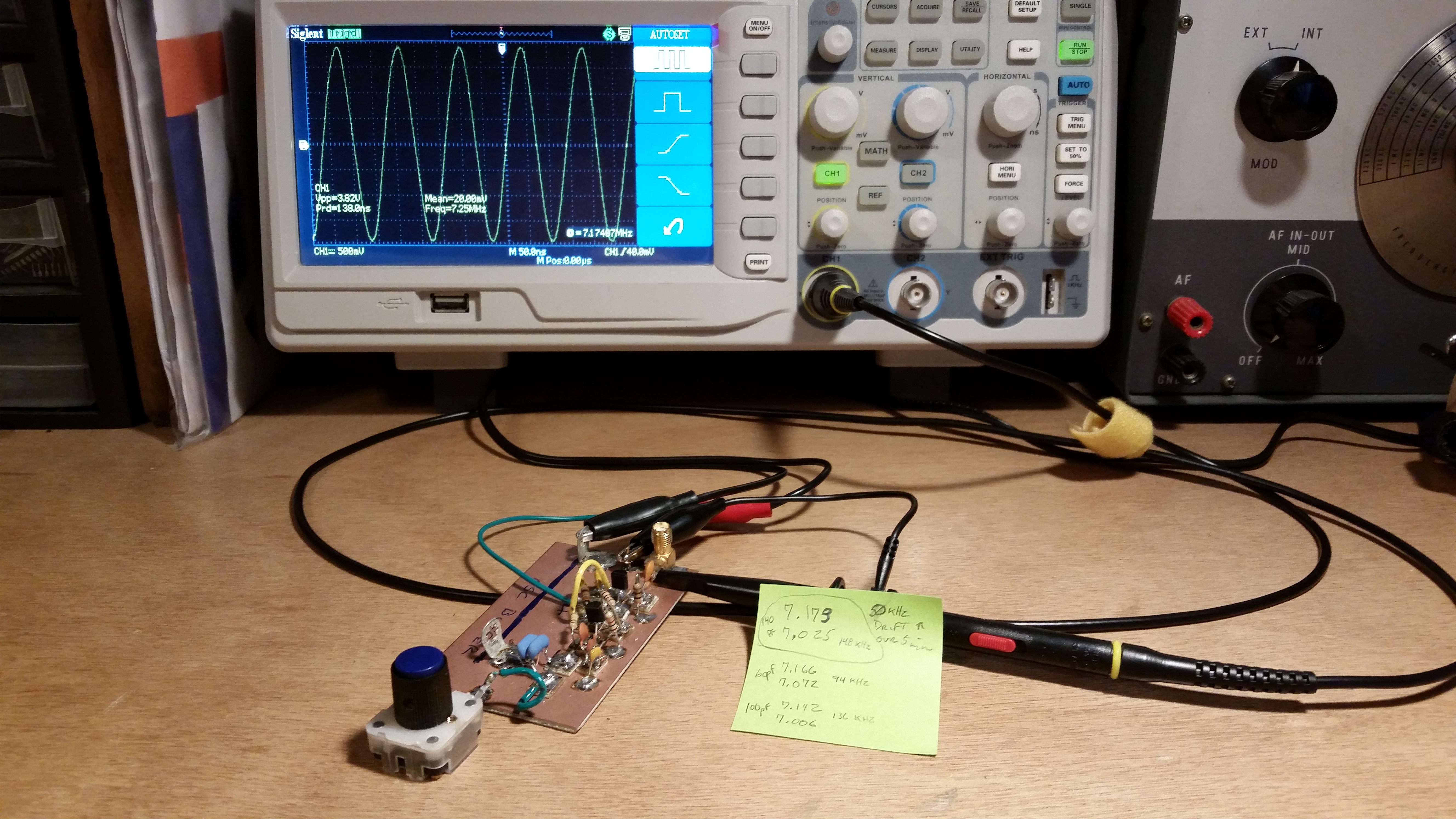
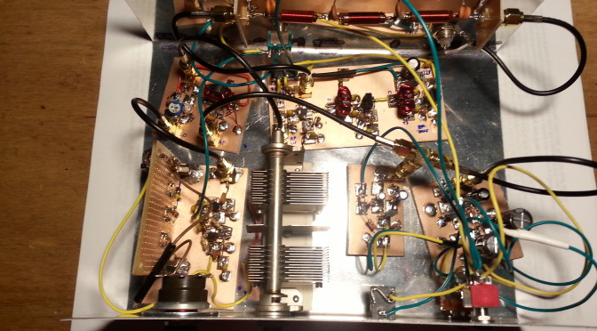
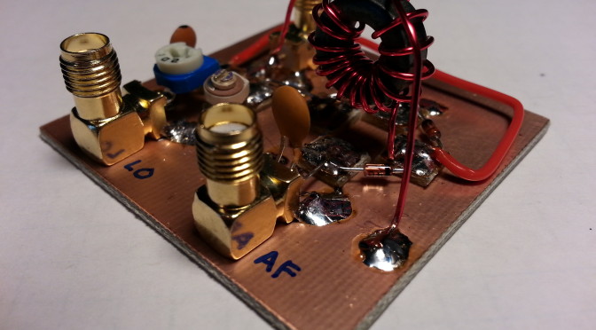
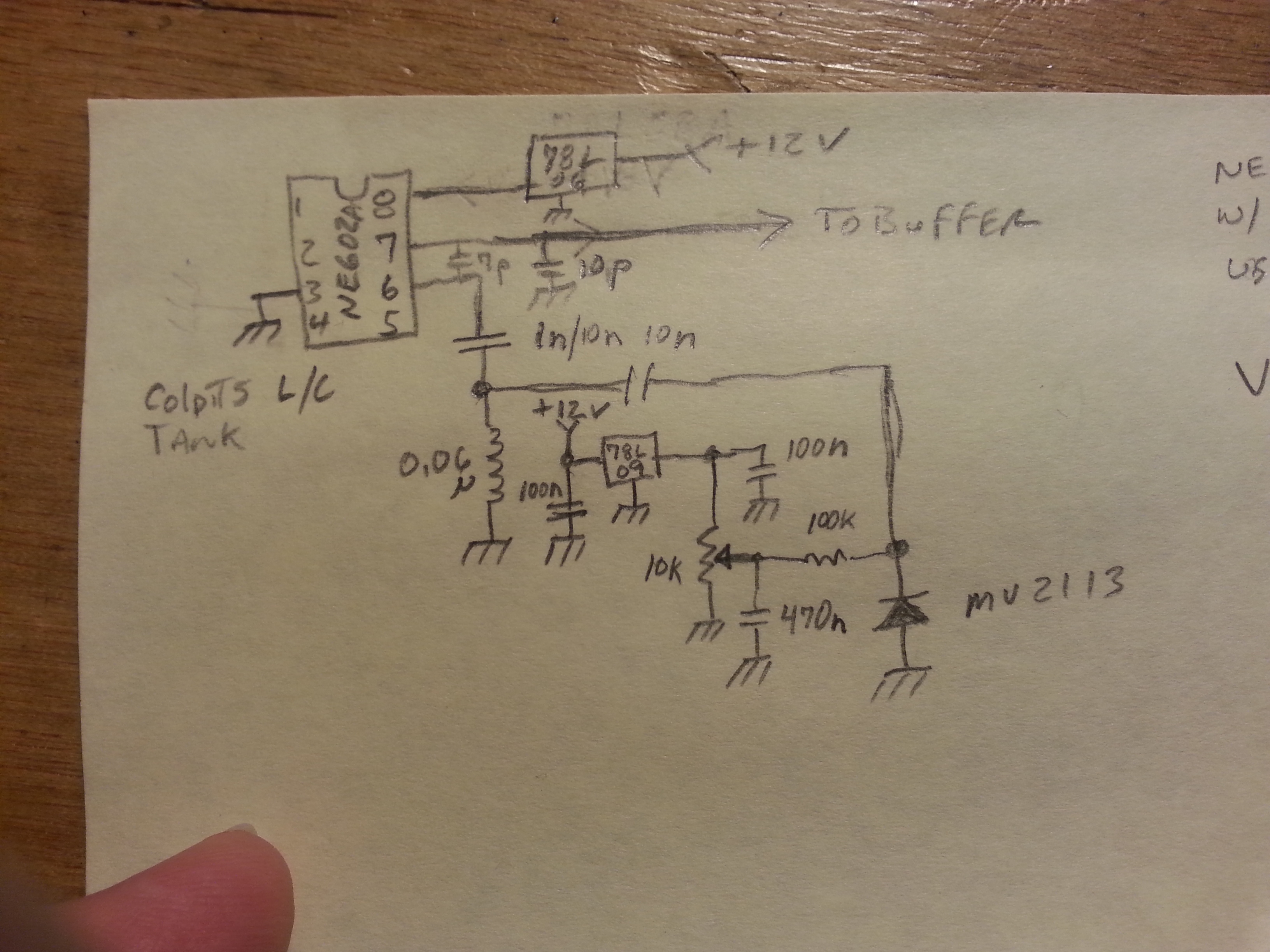
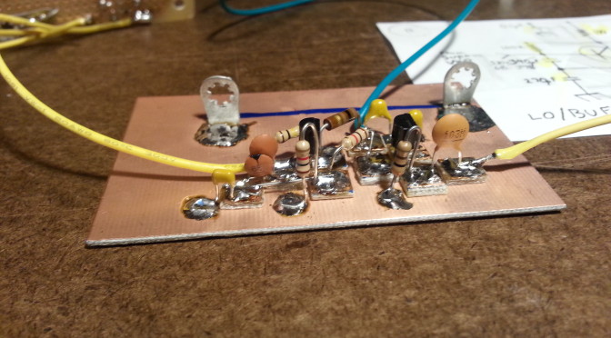
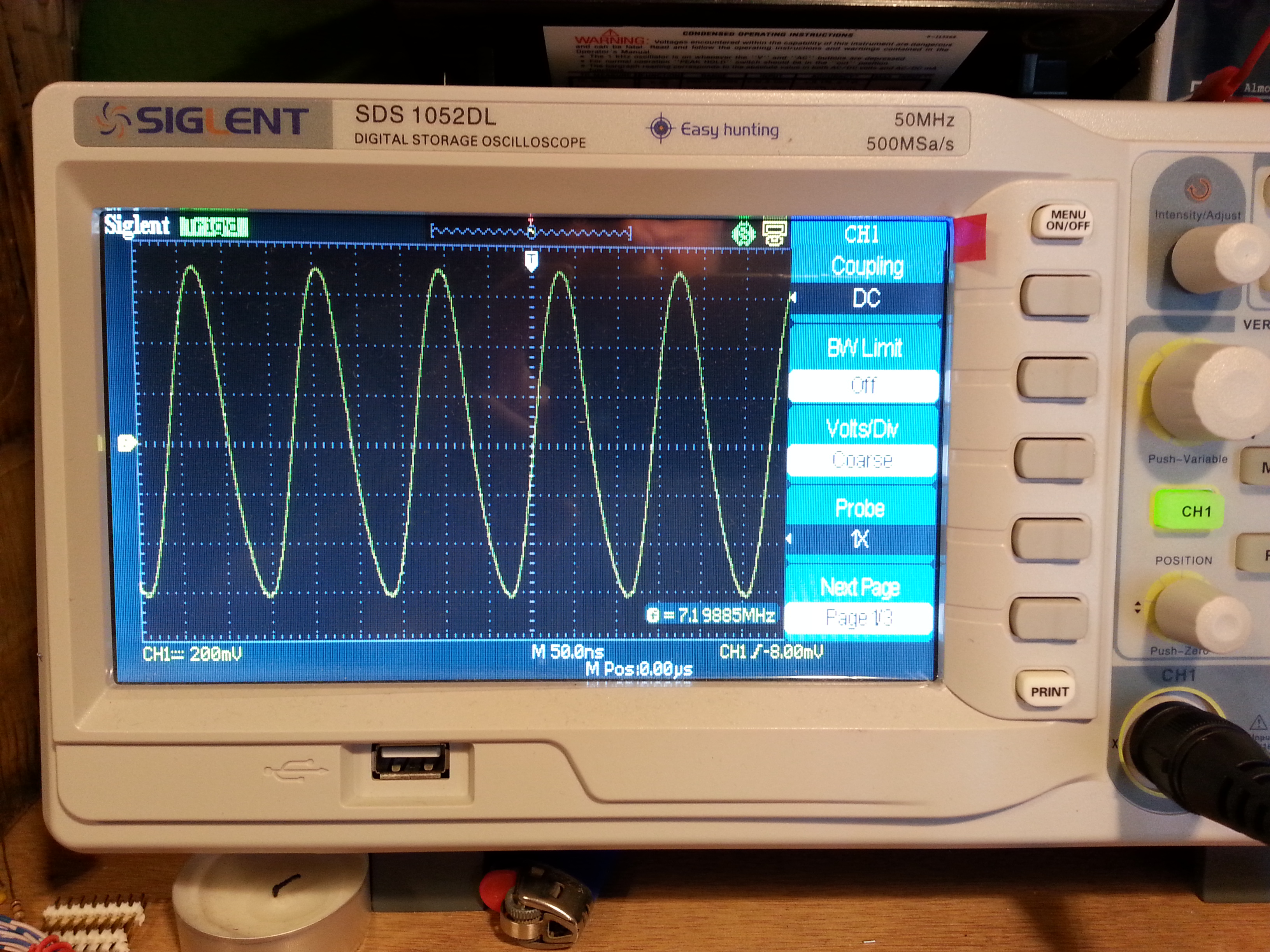
During the BitX build I ran into a small hiccough. The testing at some point calls for the injection of an 11 MHz signal. I would normally use my Lafayette signal generator but for some reason it’s on the fritz so I had to come up with another solution… build an 11 MHz signal generator.

20160622_085219
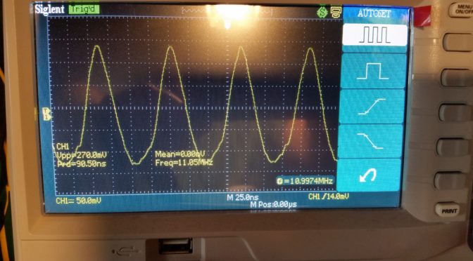
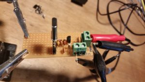
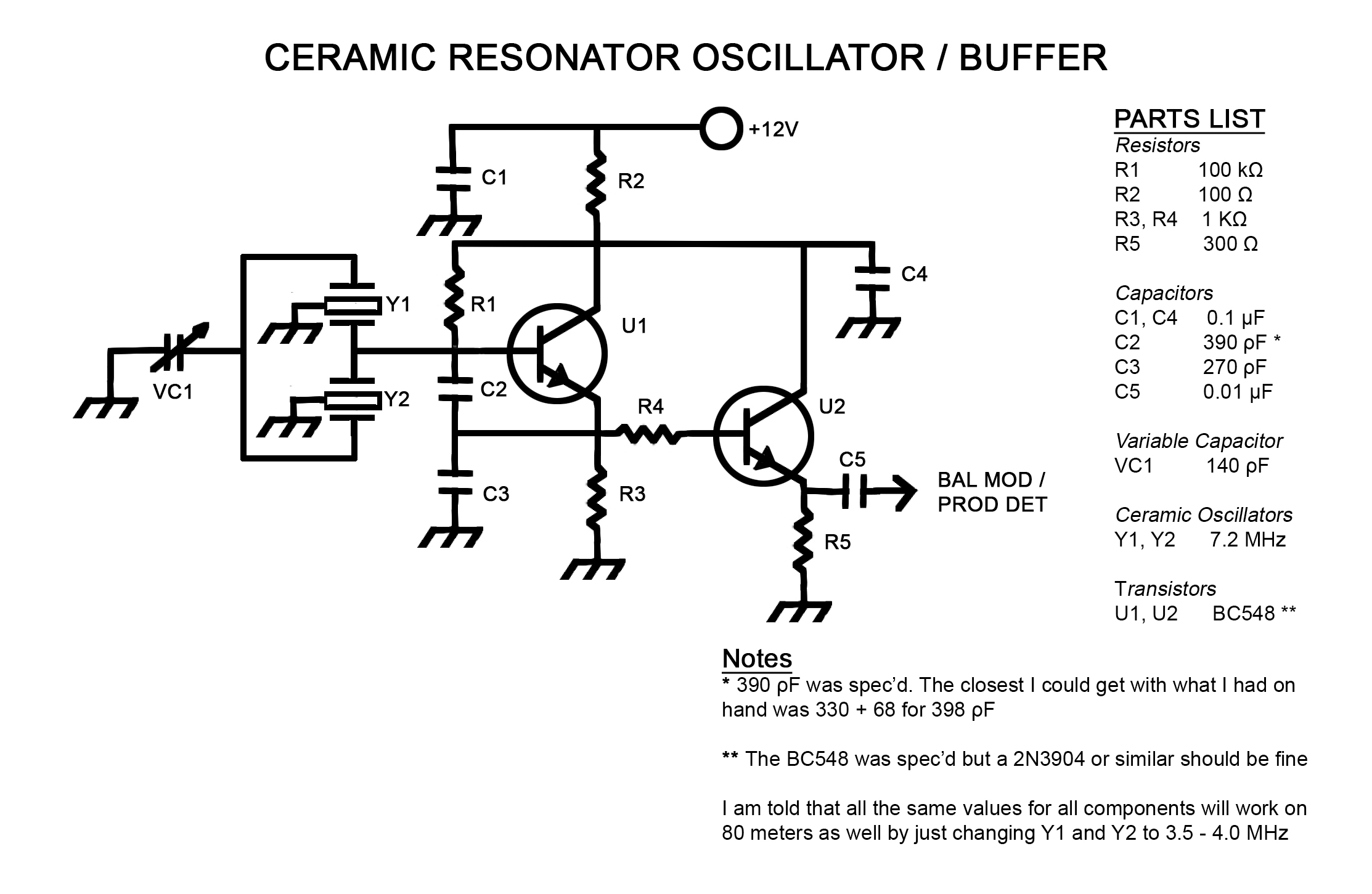
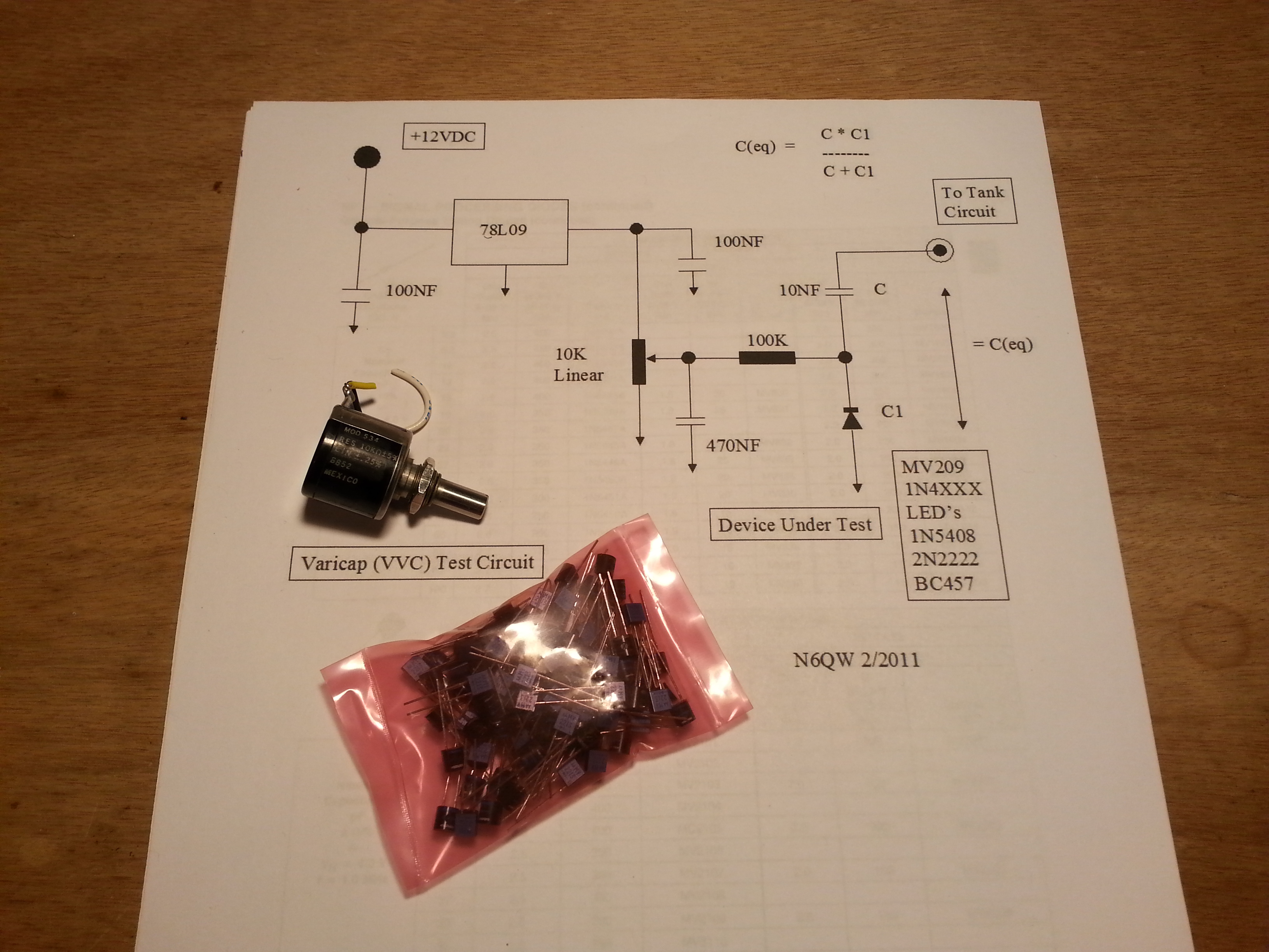
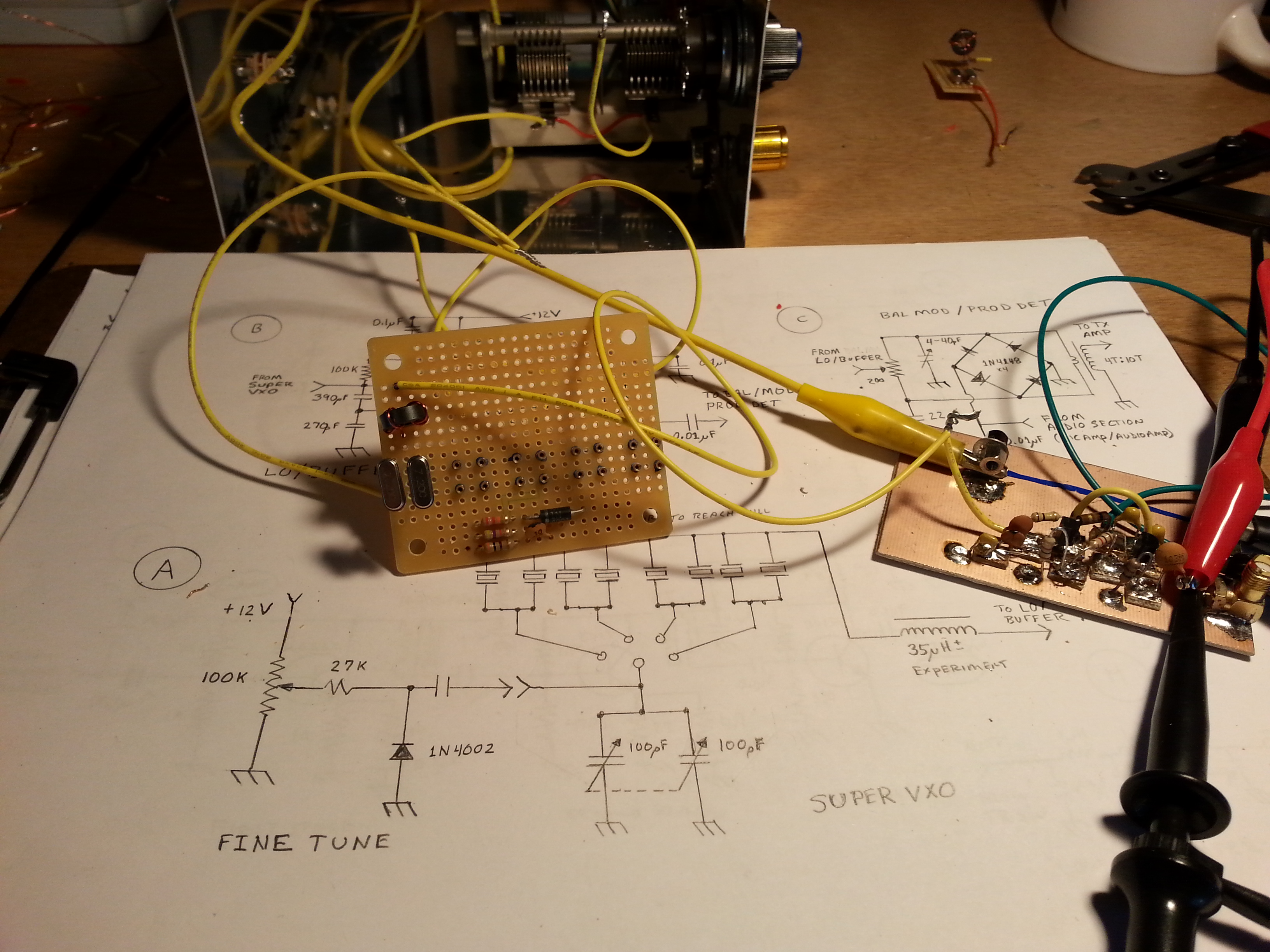
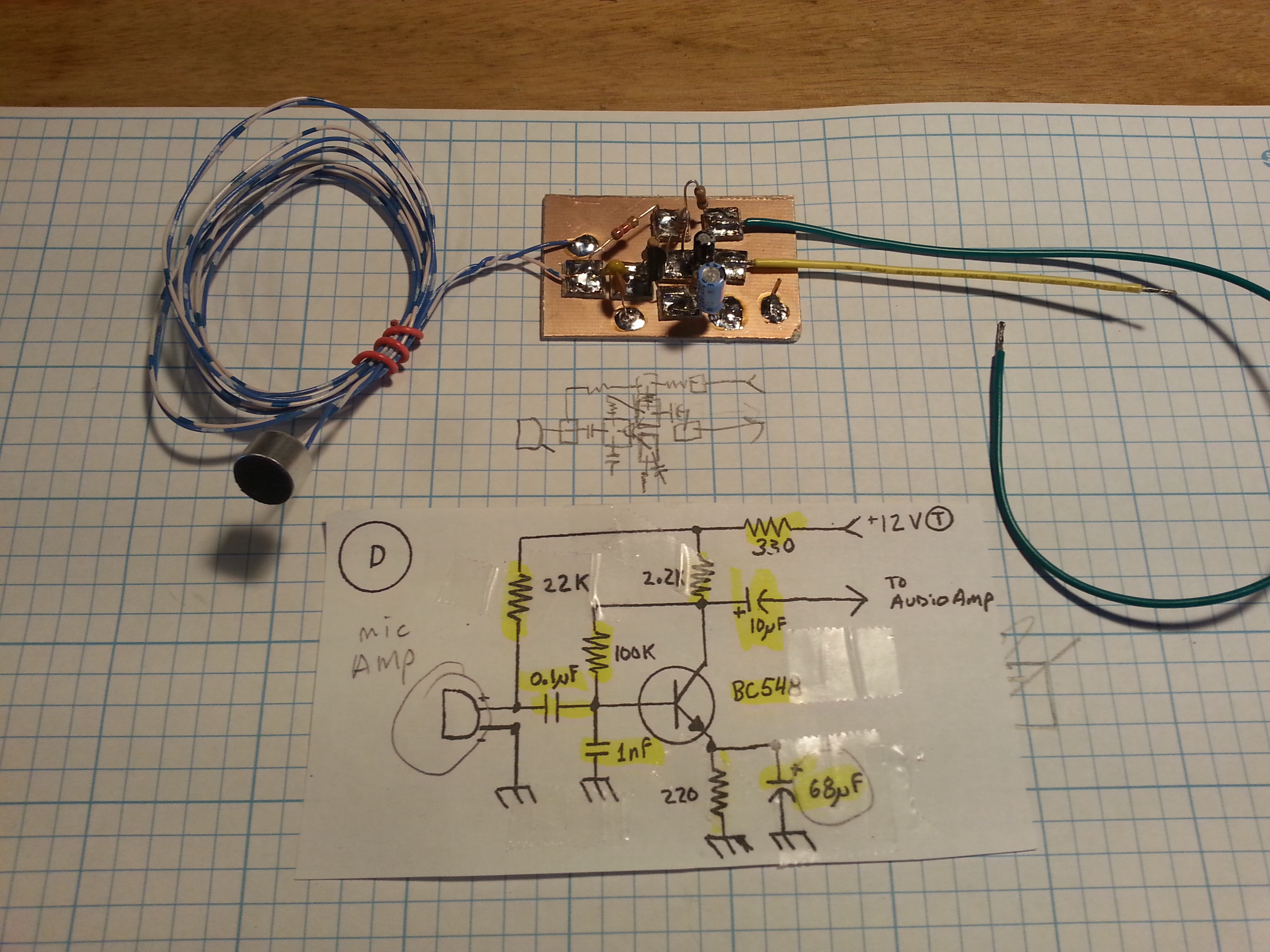
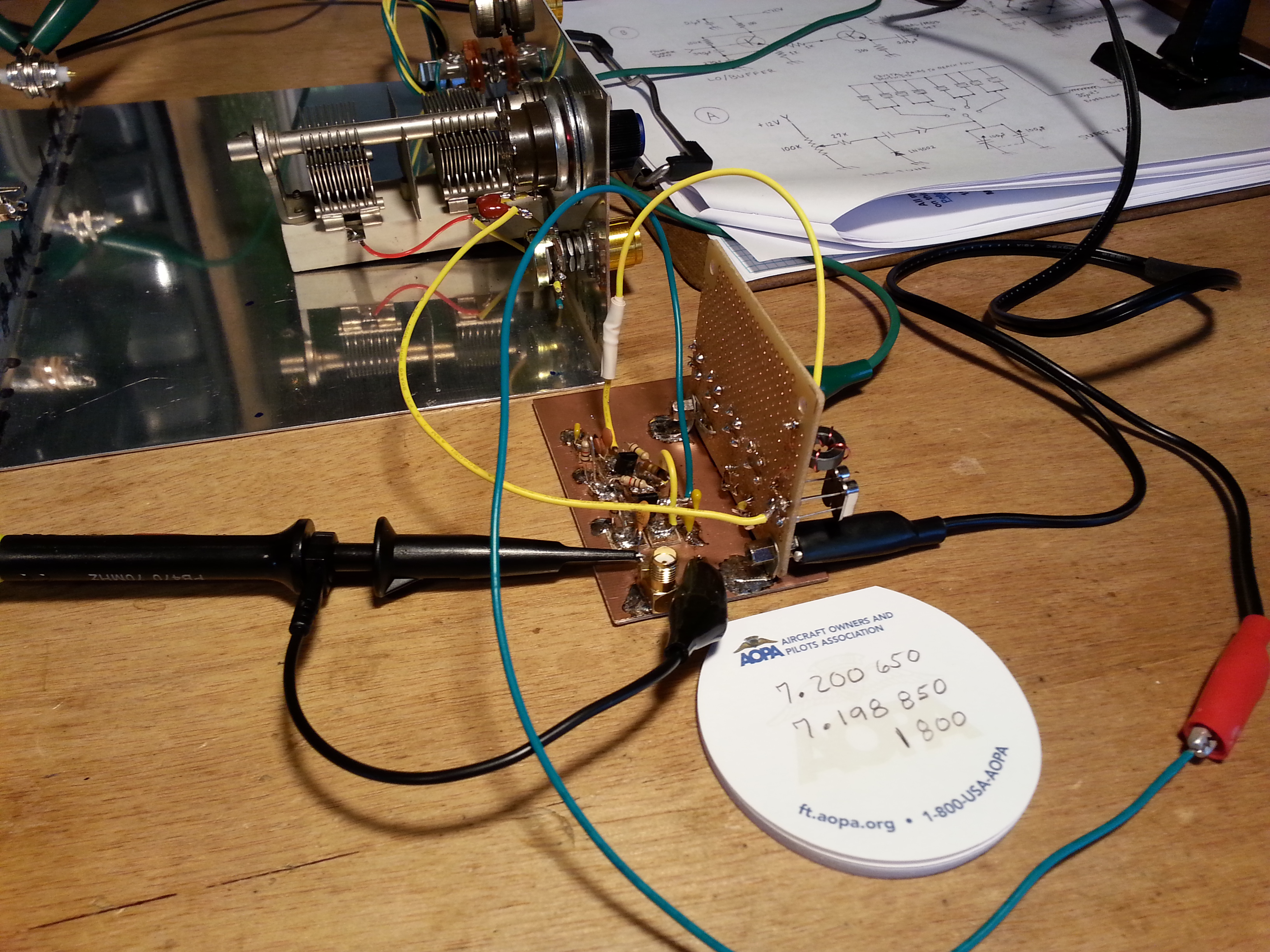
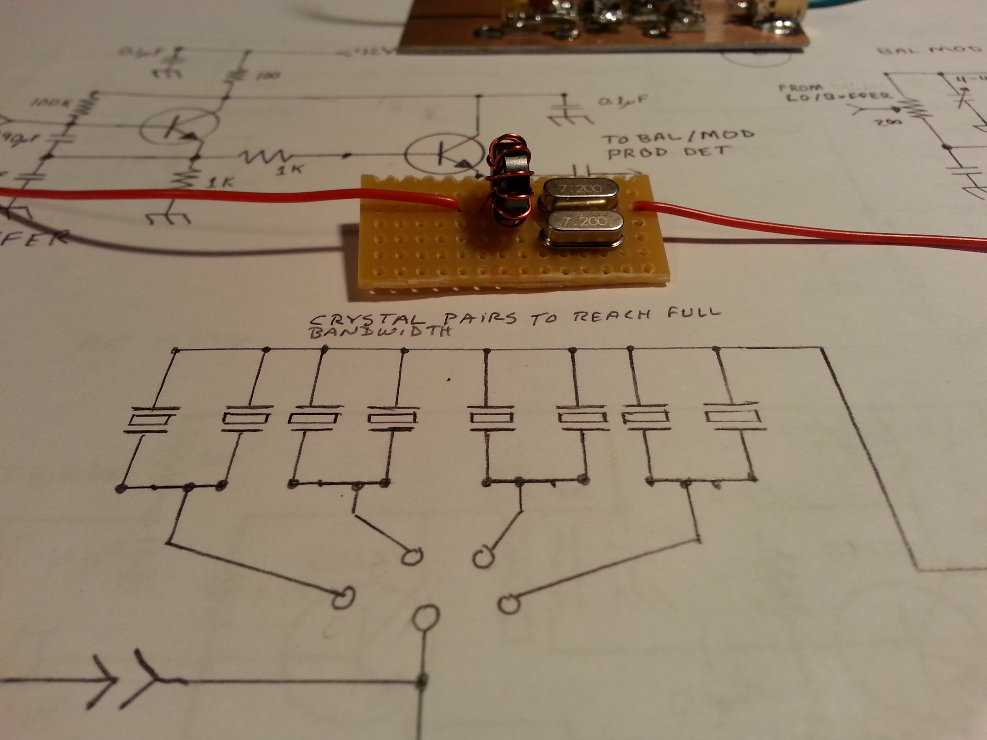
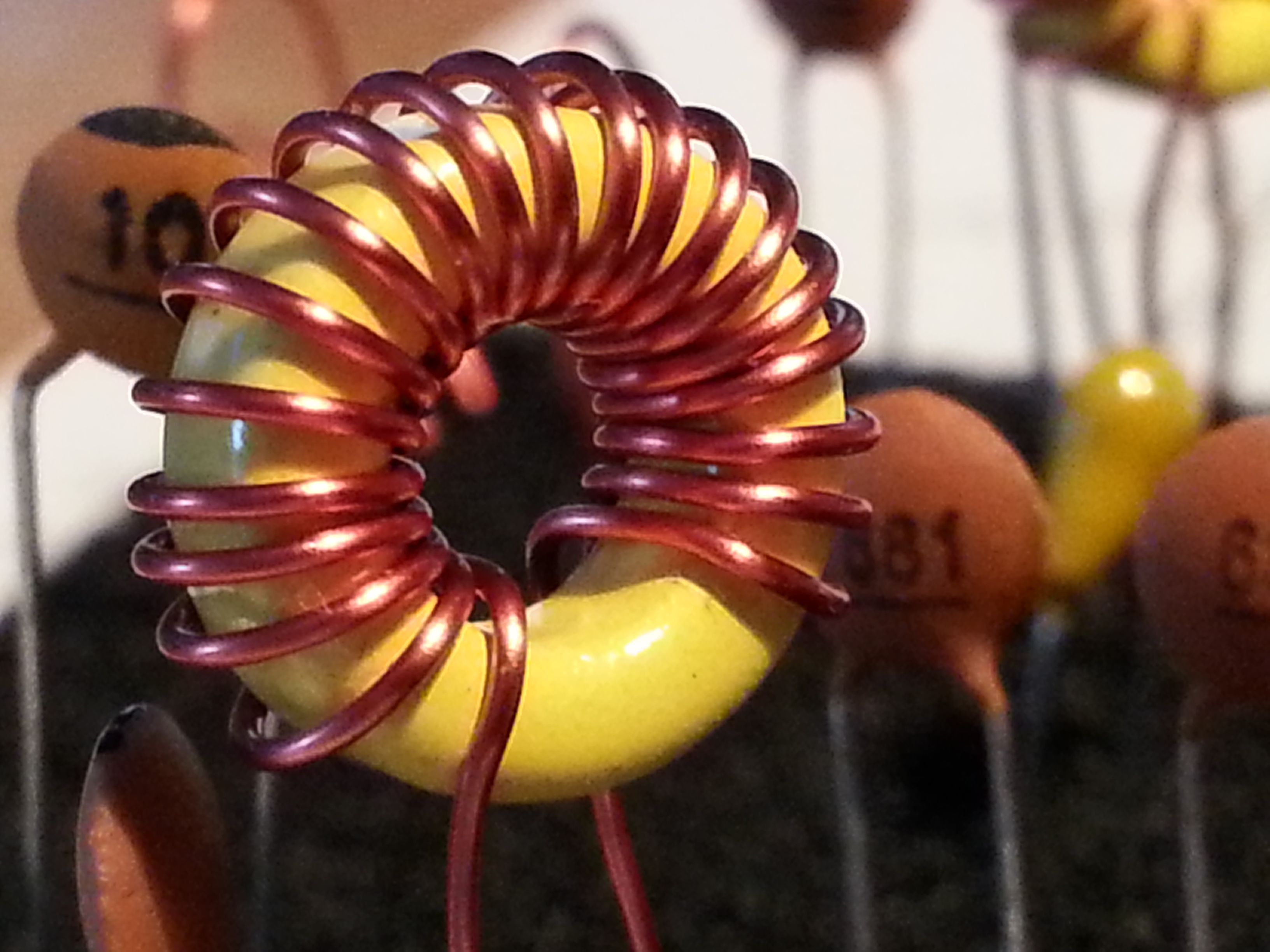
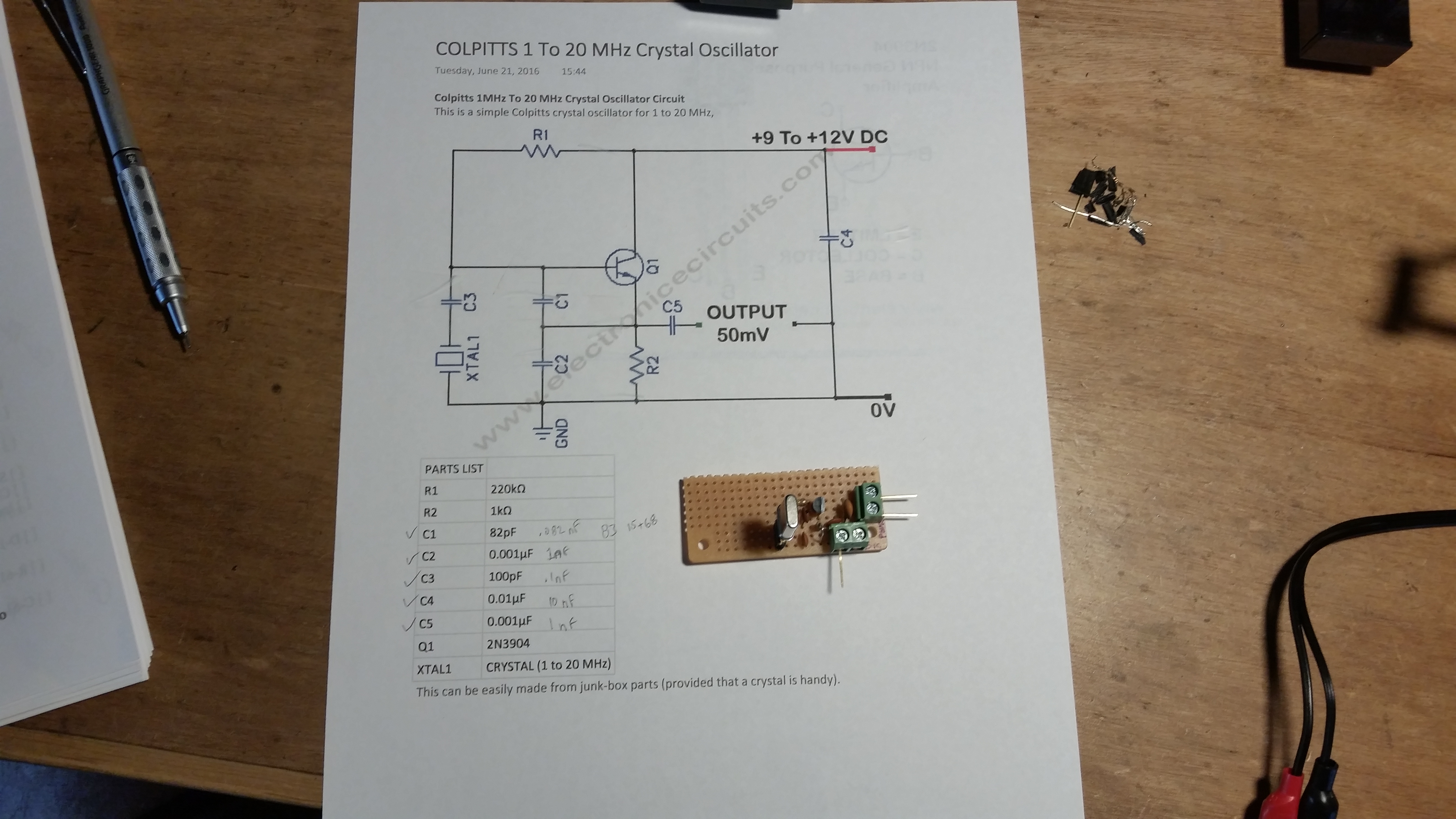
With the crystals in the kit it was easy to build a simple generator with parts on hand and while I only had 1 of the five crystals installed it was easy. By the next testing phase I had installed the remaining 4 crystals. Now I need one for the homebrew SigGen! (click the image for the circuit diagram)

Off to HSC Electronic Supply for some 11 MHz crystals.

This project will also get a write-up in the Projects section soon. This one in in particular has a lot of use in checking unmarked crystals as long as they are between 1 and 20 MHz and is a great foundation piece for beginning builders.

A Homebrew TNC

20160524_145401Before I got started on the BitX I was working on getting my Baofeng 2m/70cm HT on digital. I found a couple of designs for a homebrew TNC and set out to make that work.

Because of the way the PTT key works on the Baofeng I haven’t been able to make the TNC work with the HT but it should work fine with my 40 meter QRPme.com Splinter II and the BitX 20.

A full write-up post is coming on this one too.

Look for all three of these in the Projects section for full details on the builds coming soon.

It’s been a long time since I posted, and most of that time I have been working on non-radio stuff. Now that I am back in the swing of things I have more time for radio stuff so I should be able to post more, and make updates to the Projects pages

As soon as the BitX 20 is up and running I plan on getting the Lafayette working again and get back to the Beach 40 DSB. Another Field Day has slipped through my fingers. I don’t plan on that happening again!

That’s all for now folks, 72, 73, and good night!

~Jon KK6GXG


First week of April

Here we are, the first week of April. What has KK6GXG been up to since posting last month. Not a whole lot.

ARRL-VEC VEOne significant note, I have surpassed the 25 session count as a Volunteer Examiner! I am now up to 27 sessions. Yesterday (4/4) was also my 1 year anniversary with the Silicon Valley VE Group. I have been a VE since December 2014, but I didn’t begin working sessions until April 2015.

Working the sessions as an examiner is something I enjoy a great deal and I am always excited to see who shows up to the sessions. It is such a diverse group of people coming together in a common interest. Amateur Radio is all about diversity, and sharing common interests often regardless of  geopolitical boundaries.

I love to see youngsters at sessions pursuing their ham radio licenses, especially young ladies. While there are a lot of women in radio of all ages, it’s nice to see girls getting into radio at a young age. Radio is a place that tends to level all socioeconomic and cultural playing fields. A fellow ham is a fellow ham, period.

A couple of things have been nagging at the back of my head as of late. One is to get back to homebrew projects; get that 40 meter DSB finished and on the air. Another is to get back to studying CW, and of course build transceivers for more bands. Lastly, for now, is to get involved more.

With our QTH situation in flux for the next 6 months, it makes more sense to be involved in something less geographically ridged and that doesn’t require operating capabilities I don’t have right now or can’t build quickly and inexpensively.

This points to something administrative rather than operational. One place I would like to be more involved is with the VEC. I love being a VE, but I would like to be more involved with the process. I have no idea how I could be of service to the VEC, but I would like to.

Another thing I want to do before we change QTH is get back to the Bay Area Builders Club monthly meetings. Fortunately this one is just a matter of making the time to get over to the meeting. See you guys on Sunday 😉

KK6GXG-MakingWavesNo concrete plans, just some aspirations. For the moment that’s all I can muster. Life and the Day Job have been at the forefront but no playtime makes for cranky-pants, so I need to figure out a way to make some time. This post is one attempt at making some time.

Til next time… 73.
~Jon KK6GXG

Another month gone by

foto001mdOkay, it’s now March 11th, and I have done just about NOTHING radio related except attending VE testing sessions since what, December?

Not entirely true I suppose. I pulled down the 70cm and 40m antennas from the Hillbilly mast rig, and I have done some poking around at the 40m DSB project, though I haven’t done any real work on it.  Also the VE sessions have been a saving grace in many ways. One, I am still “participating” in the community. Two, we have been engaging is some interesting discussions in the back of the room while waiting for exams to grade. Three, I did reach a milestone in so much as I sat my 25th session this last Saturday. That at least, is something I can honestly say I am proud of.

There are so many projects I want to get going on, I just can’t justify the time right now.  The family is working towards a relocation up to northwest 7 land, and I am really looking forward to the move. There is just so much swinging in the breeze right now, making any plans or starting any projects is just not a good idea.

We are heading up north in May to look at some property. We are hoping that this trip will provide a target for relocating by the end of September at which point, all hell’s gonna break loose and I’m going to be a very busy man.

I have no idea what I will be able to do radio-wise between now and then. I do know I am itching to do something though. I will just have to see what opportunities present themselves in the meantime.

73,
~Jon KK6GXG

40 Meter Ceramic Oscillator

The Beach 40 saga continues. My original VXO design, well… it stunk. I’m not sure why, but the best selectivity I could get out of it was only a couple of kilohertz, very annoying.

20151104_161508

I have been working on a VFO design to get full band selectivity but in the meantime I came into some ceramic oscillators for 7.2 and 3.68 MHz. The best part is that I replaced the entire Super VXO section with a 140ρF variable capacitor and two ceramic resonators.

20151104_161541

By placing the 140ρF var cap in series with the two paralleled resonators and feeding the output directly into the local oscillator buffer… Ta da! A working  VXO.

This time, instead of a few kilohertz the VXO pulls a full 148 kHz, from 7.173 MHz down to 7.025 MHz. It is certainly not the full band but it is a useable range. Over a five minute period, I noticed a slow 50 Hz drift that eventually settled out to a point where it continued to float ±10 Hz.

20151104_161453

This is not a final solution, but it will work well enough to get this QRP DSB transceiver on the air for testing.

Of course now that I have a working VXO attached to the local oscillator buffer, it’s time to hook it up to the product detector/balanced modulator… success! With the VXO, buffer, product detector chain attached to an antenna it was time for a little listen.

20151104_163742

The audio amp still has some issues as far as power drain off when power is disconnected, but it does fine as an amp. I plugged everything together and plugged the audio out into an external amp so I could tune around without headphones.

Not much on the band, but my frequency generator with a small antenna plugged into it put out enough RF for the receiver chain of the Beach 40 with the temporary VXO to pick up its 400 Hz signal and cross reference the VXO frequency displayed on the oscilloscope with that of the frequency counter connected to the frequency generator. So one could say I have a working receiver, mostly anyway.

Next up: First and foremost I need to get my documentation in order. In particular, I need to get the schematics in conformance with the actual circuits.  After I get the documentation in place I need to get to work on the audio amp.

After the RX stage is all dandy, my attention will turn to the TX/RX switching. I can’t do anything more with the TX side until I get the TX/RX switching squared away.

Anyway, that’s all for now.

Until next time,
~Jon KK6GXG

UPDATE: As promised, the conformed schematic for the VXO/Buffer section…

Ceramic Resonator VXO

Slacker Week

Oh, I’m a baaaad boy…

I have been busy, but not so busy that I couldn’t get a small post up, what a slacker. I just wasn’t up to it, so this week is catch-up week.

20150615_105153
The clear bins on the left replaced one of the black drawer units and brought a bunch of stuff up from under the bench

One thing that got done was making some component storage changes on the benchtop. There was a bunch of stuff under the work surface that if I wanted a component I had to pull out and unstack containers to get to parts. Now most of the components and parts are on the benchtop. Staying organized is hard work. 😉

The Beach 40 is getting closer to completion. I have all of the sections done(ish), I need to go back and swap out a pair of capacitors in the Audio Amp and test the RF Amp section. The biggest thing I am behind on is posting updates to the project page which I will be doing this week.

I have a bunch of day-job stuff that I need to get done this week as well so it will be a bit of a crunch on time so I don’t see much solder melting in this weeks schedule but I do believe I’ll be up and running for Field Day, *knock on wood*.

On Saturday the De Anza Electronics Flea yielded some sweet fruit. A very nice edition of Andrew P. Peabody’s 1873 A Manual  of Moral Philosophy in great condition. Another awesome find was a Millersfalls No. 2 egg beater style hand drill, also in really good condition. The crank handle needs a little straightening but the drill is in great condition for daily use. Last but certainly not least was a bag-o-relays. Which is what I was specifically looking for at the flea. Thirty eight relays, all good for radio work, and only $20.

A really good flea market day, something for the mind, something for the hands, and something for making radio waves. What more could I ask for.

Sunday was the Bay Area Radio Builders Club meeting in Cupertino. A small gathering but plenty of radio building chin-wagging along with some show-and-tell. Topics ranged from my DSB transceiver to a Raspberry Pi controlled HT set up as an Echolink station with many more abilities under the hood, and the clubs TAK-40 radio build progress. (TAK-40 link to QST magazine article PDF)

That’s all for now, the day job beckons.

Until next time, 73,
~Jon KK6GXG

Solder-less Progress

Some good stuff got done this week even though I didn’t melt much solder.

I had an amateur radio testing session on Saturday. It was a busy day with lots of new hams passing there Technician, some going on to pass the General exam, and even an Extra! We also had several upgrades to General and Extra.

For me the session was also a good learning experience as a VE because I had the opportunity to get some training in another job with the group.

We basically have three jobs split among the VEs present at any given session; two administrative jobs, and a panel of test examiners.  I have been participating as an examiner for the last several months. Today I received some training for the administrative side of things.

I have been putting off the testing on the Beach 40 until I get the last few details finished on the audio and RF amps as well as the LP filter. This week I am playing beginning of the month catch-up with the day job so time is short.

Also tied to everything else is the change over from Windows to Linux. I have deleted the Win partition on the laptop and am now running full on Linux. I am loosing two programs I liked but just couldn’t get them to work with Linux native or emulated and I don’t want to run virtual machines. I still have all of the data, and I do have a Windows 7 laptop in the shop I basically only use for the web browser.

The programs I am loosing are Quicken and Business Plan Pro. BPP will just go away. I exported all of the business plans I have put together over the last decade to .doc files which I can access through OpenOffice. I can use the previous plans to build new ones as needed in document formats.

Quicken is the one giving me headaches. Supposedly you can export the data to a file for import to Skrooge. No joy. After several exports and several hours I made the contagious/stupid decision to just go back and reenter all the data for this year.  It sounds a lot worse than it is. I will just do one month at a time and by the end of this month I should be all caught up. Not to mention very familiar with the new software.

I have found replacements or versions that will run on Linux or in emulation for all of my radio software an in fact found some new stuff that looks mighty interesting. Big plus here.

Along with the radio specific software, I found gEDA Schematic Editor. WOOT! It took a little getting used to the interface and component placement, but I like the results a lot. I have been redrawing the schematics I originally did on schematics.com for the Beach 40 and think they look much better. I will be posting them soon to the build page. A good thing too because there are some errors on those schematics. Ooops!

One last update before I go, I was working on test prep for my commercial radio license a while ago but got sidetracked by all of the build projects and the day job. One of my goals for second/third quarter is to take my commercial radio exams, at least two of the three anyway, and get my commercial license. So I will be committing some of my limited time to that endevor over the next few weeks. The build will continue, I still hope to have the Beach 40 up by Field Day, but I need to budget more time to the Day Job/Future Day Job.

Anyway, I have 0.5TB of files syncing with Google Drive and a pile of accounting stuff that needs to find a new home in Skrooge so that’s it for today.

Until next time, 73,
~Jon KK6GXG

Back to the radio

KK6GXG-MakingWavesTo keep domestic peace I have not been building on the Beach 40 non-stop as I might otherwise do and there is a side benefit… By taking some time away from the build I can clear out the cobwebs and refocus on the greater project to check my thinking and my work.

I still need to do testing on a few of the sections. However I have all but two sections assembled with only minor followups. I need to figure out the value of the common emitter voltage limiting resistor on the Audio Amp and I need to wined and connect the two bifilar toroids in the RF Amp.

T_R Switch
Not a literal schematic, just a rough idea

The last two sections to build are the Low Pass Filter and the T/R Switching sections. The bit that I have been burning cycles on is the T/R Switch. I want to do something that consumes the least power overall at-rest, something basic and bulletproof.

My current thinking on the T/R Switching is a pair of relays, one NO and one NC. RX on the NC and TX on the NO. This way everything is normally in the at-rest state and I only need to run one power lead from the TX momentary switch to both power leads on the relays. Since I don’t have the relays in stock I will need to go get a pair. Sounds like a trip to HSC. 🙂

Once I have the relays I will draw up a new schematic for this section and get it posted on the project page.

While not working on the Beach 40, I did do some radio stuff. I picked up some parts for stock from Jameco one day, a bag of varactor diodes, then two days later went back to pick up voltage regulators, a bag each of 5, 9, and 12 volts.

The XYL went with me to a local Radio Shack that is closing down. We picked up a bunch of zener diodes, a pair of bridge rectifiers, and some mechanical connections at 80% off. There wasn’t much left to pick through. I also found a pair of NO SPST relays which got me thinking more about the previously mentioned T/R switching circuit.

I also ordered a few bags of various op amp transistors that are frequently used in radio circuits. Purely a stock order, and I’m pleased to say the parts bins are slowly filling up and I am getting to the point I think I could actually build my next radio without going out and buying any parts. This is a good thing and I’m fairly certain my wife will agree.
Sneak Peak: I’m thinking about a Beach 20…

Also radio, not Beach 40, the beginnings of research on VFOs. I have been looking at a lot of material on VFOs without finding what I am looking for. I want something small physically, low power consumption, as close to all discrete components as possible, all readily available parts, stable, and a wide tuning range. A tall order I think.

20150603_105313
First pencil sketch, next into the lab book and beyond

A first design only slightly out of specifications is this one I worked up from a test circuit diagram from N6QWs VVC page and the NE/SA602 spec sheet. It will be my VXO-X01 build. 😉

An Experiments page has been set up to keep a log of these kinds of long-term projects. I haven’t created the page for the VFO research yet but that will be up shortly after I update the Beach 40 build page.

One other non-radio, well mostly, is the slow planned migration to Linux. I have been wanting to this for a long time but the last time I tried it wasn’t so well planned. This time I am running both Linux (Ubuntu) and Windows (8.0) side-by-side rather than one virtual. It will be a long protracted process this time but it should result in a much better transition.

That’s it for now. Trying to keep the smoke inside the parts where it belongs until next time,

73,
~Jon KK6GXG

40 Meter DSB Coming Soon

Busy weekend for me.

20150530_161129Before moving on to Beach 40 progress, I got something else in the mail. A frequency counter module I ordered off eBay for ten bucks. I am thinking about using it in a future radio project as a digital frequency display.  Not sure what project, but it beckoned to me and I figured it might work out well.

20150530_221434In a related sidebar, I have been doing some VFO research. I have been looking at several options and one that seems simple and efficient is using varactor diodes to replace the air dielectric capacitors in tuning circuits. I have some ten-turn potentiometers and found a good deal on Motorola 68ρF varactors so I bought a bag of 100.

I found N6QW’s website with some great information including a test circuit for testing the tuning abilities of various diodes and transistors. Definitely more to come on this venture after the DSB project is done.

Now, on with our regularly scheduled program…

20150529_164741In the last post I talked about skipping the Balanced Modulator/Product Detector and moving on to the Audio Amplifier.

I built the Audio Amp and got everything all tied in to the panel mount components.

20150529_165009I still haven’t tested the Audio Amp yet and I am saving that for after I get all of the sections built out.

About the time I finished up the Audio Amp the 200Ω potentiometer I was waiting on showed up. With the parts in hand, I moved on to the BM/PD.

20150527_153801The BM/PD build went well. with no real surprises.  The diode ring ended up being laid out in an actual ring configuration with the RF transformer being mounted right in the middle.

The one thing I don’t like about this layout is the really long lead from one side of the diode ring all the way around to the other side of the board to the potentiometer. I don’t know if I can come up with a better layout in a future rendition but for now it should be fine.

20150530_214234One of the first things I started with today was building the interconnect cables out of RG174 coaxial cable and SMA connectors. I considered MMX connectors since they just push on rather than thread on but they are way expensive. I have seen a number of builders use coax interconnects for modularized construction and it makes separation for experimentation much easier.

20150530_220849One cable I made was actually an antenna, a test antenna at least. For testing transmission sections giving them something to radiate out of. By using a receiver near the transmitting device I should be able to copy the transmission. It’s the one on the right if you hadn’t guessed.

20150531_110751Cables, of any kind,  are one of those things that can seem fairly easy to do, but when they go bad, they can go epicly bad and it can be hard to detect. The only preventative effort I know of is to take your time, use a light touch, don’t force things, and pay attention to detail.

I made 4 interconnects, 1 antenna, and one single end cable for connecting to the antenna outlet. It took a coupe of hours, but all of them are solid mechanically, and test to be solid electrically.

20150530_221209After getting the cables done, I hooked up the antenna and one of the interconnects but I still haven’t done any of testing beyond the Local Oscillator.

I have a lot of testing to do but I’m almost done with the modules so I wanted to plug away and finish up the modules.

20150531_143223The last thing I worked on before turning off the soldering iron was the three stage RF Amplifier.

The pic is the first stage, a buffer stage. I started the board with a configuration in mind but by the time I got to the third stage I had shifted a few things around.

20150531_150232One thing I wanted to point out is the spacing of the stages. In this pic I have most of the second stage done and the pads for the third stage laid down. The gaps between stages are for the addition, if needed, of shielding between the stages. This amp is fairly low power so I don’t think it will need the shielding, But I wanted to make the option available.

20150531_161643The third stage saw several pads moved and things reconfigured a little. The yellow leads are the RX Amp Bypass (short lead) and Amplified RF (long lead) lines going to the relay circuit which after a lot of thought this evening will be replaced with cable ports and the relay section will be moved off this board entirely onto it’s own module.

The other bit on the RF Amp board that still needs work are the two bifilar toroids that still need to be wound and installed. It sounds like a lot of work still to be done, but it is getting very close to First Contact.

Thats all for this post. May the magic smoke remain contained in all your circuits.

73,
~Jon KK6GXG

RTFM aka Read The Datasheet

A lot going on these days. Lets start with something educational… No, don’t run away… it’s not that bad.

RTFM or Read The Freaking Manual is directed in this case to datasheets for semiconductors. And this is where we begin our lesson for today.

20150527_113247
The VXO dismounted from the LO/Buffer for testing

I have been working on the Beach 40 project for a few weeks now and have made some progress but I was having some difficulty with the VXO (variable crystal oscillator) and the LO/Buffer (local oscillator and buffer.) The oscillator section is supposed to generate an RF carrier frequency, in this case close to 7.2 MHz. I wasn’t generating the carrier and I couldn’t figure out why.

I decided to put these sections aside and move on to the next section and ruminate on the problem for a while. The next section in line was the Balanced Mixer / Product Detector but I was missing a component that I was still waiting to arrive, so on to the next stage, the Microphone Amplifier.

20150525_135559
The Mic Amp has the mic element temporarily direct wired for testing

Laying out the parts physical locations on the circuit board I came to the transistor, one I hadn’t worked with before. So I decided to look up the data sheet and be sure of the pin-out. It wasn’t what I was expecting it to be, and then it hit me, like a Log from BLAMO! My oscillator wasn’t oscillating because I had the pinout wrong on the transistors! I finished the Mic Amp and the part arrived for the BM/PD.

20150527_154019
The Balanced Mixer/ Product Detector. Ain’t she a beaut!

I moved on to the BM/PD and finished it then looked up the transistors on the LO/Buffer and sure enough, I had them in backwards.

With a little coaxing and cajoling, and construction of a really scaled down crystal oscillator for testing, I got them turned around and everything back in place, well sort of. I missed a jumper and had to go back and solder that back down, but the after that the oscillator was oscillating like a good little oscillator should. Oscillation!

With a little tweaking and and the removal of the Fine Tuning circuit that I still haven’t figured out, I am back on track and only three sections shy of a full transceiver.  At present I have the sections built for a QRPpp transmitter a very, very, very, very low power transmitter, somewhere around the microwatt range but I should be able to modulate a voice transmission a foot or so to my DC receiver.

The Mic Amp test is actually a test of the VXO, LO/Buffer, Balanced Mixer, and Mic Amp sections and has me transmitting some AF (audio frequency) along with the carrier through the Balanced Mixer to help locate the signal in the band. Once I locate the signal on a separate receiver it’s time to tune out, or “suppress”, the carrier signal on the BM/PD section.  I’ll be doing just that in the next few days. Hopefully I will remember to video the test and post the video.

I already checked out the VXO and LO/Buffer when I checked the frequency. I can check the Mic Amp just by hooking it up to a speaker, which I will. Then the BM/PD gets it’s big on-air check out.

20150527_163139
CCW from top left: Balanced Mixer/Product Detector, Local Oscillator/Buffer with VXO mounted vertically, tuning capacitor, Mic Amp, and Audio Amp with just the tinned pads on the board

All that’s left to have a working receiver is building the Audio Amplifier which I have already laid out, I just need to solder the parts down and test. After that I need to build the RF Amp to have a transmitter. I will want to also complete the Low Pass Filter before transmitting though. I don’t want to splatter the band or anything.

So the schedule for now looks like a completed Beach 40 transceiver should be on the bench next weekend or there abouts.

That’s all for today.

73,
~Jon KK6GXG

The AADE L/C Meter IIB

If you don’t work with RF electronics the need for an L/C meter may not be readily apparent. If you work with RF, you have likely found capacitors and inductors in the junk pile and played hobb trying to figure out the value, unless of course they were marked.

My first homebrew toroid inductor. Aint she purdy?

If you wind your own inductors or make your own capacitors the need for an L/C meter is a no-brainer. I bought a cheap Chinese manufactured meter and it was no bueno. No redeeming qualities what-so-ever.

Within the Amateure Radio world AADE (Almost All Digital Electronics)  and the L/C Meter IIB has earned an almost legendary reputation for being just the piece of equipment the homebrew ameture needs.

20150518_173544Being a homebrew ameture and a recycler of electronic components, I decided to buy the L/C Meter IIB kit and build it. The kit itself is very straight forward. Assembly is well documented and easy to follow.

I have been generating a lot of solder smoke lately so I may have an advantage here in assembly speed but I went from shipping box to functioning test equipment in about 4 hours.

20150518_194352Starting with full parts inventory I went right into construction. The parts list is only one sheet and it is very detailed. After checking in all of the parts and tagging them to the parts sheet I fired up the soldering iron  and started melting metal. Filling the printed circuit board didn’t take long at all.

Th20150518_212344
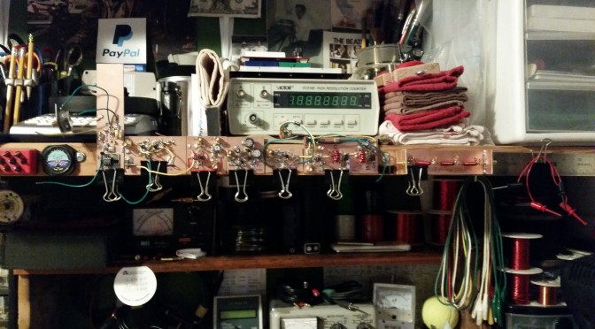
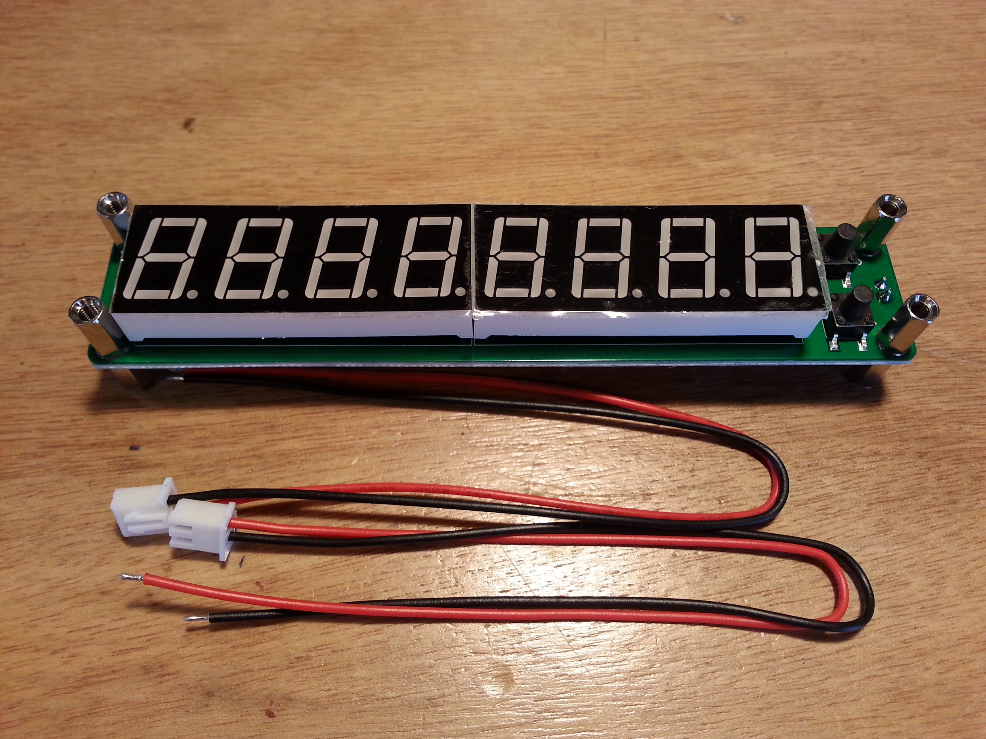
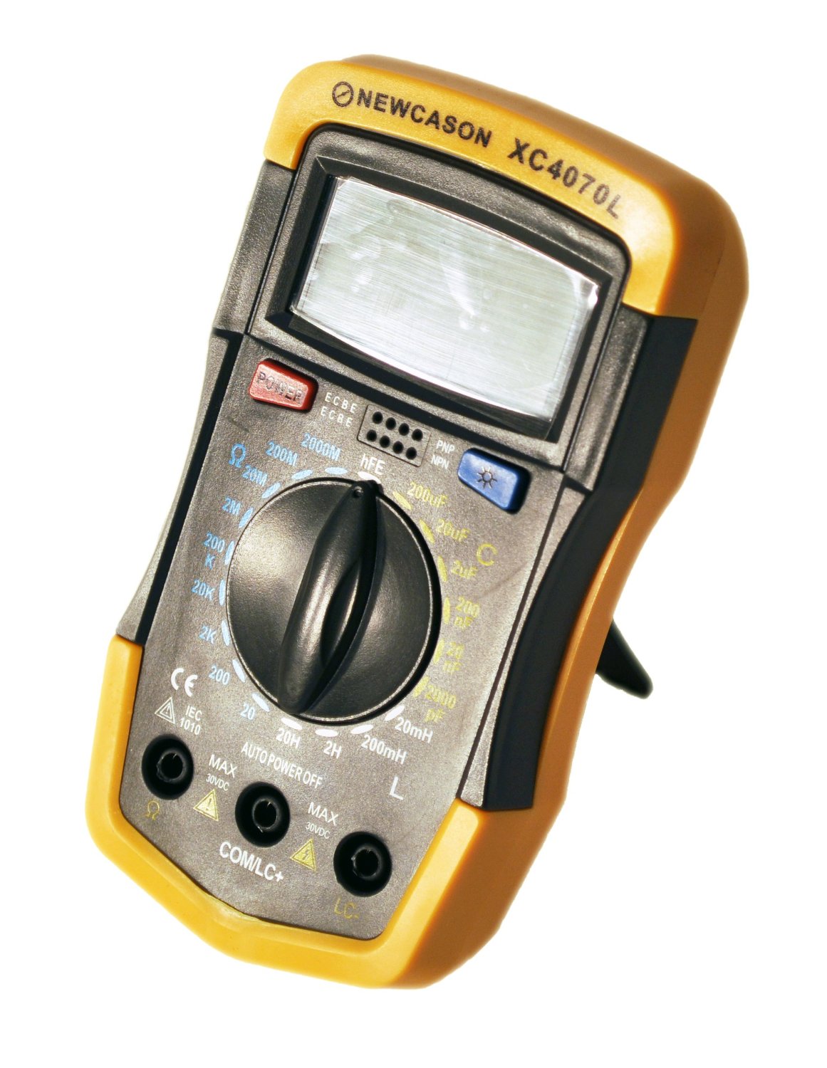
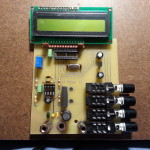
e only hiccough was technician error. I got all of the components soldered in, mounted the board in the back of the case, mounted the LCD, and plugged in the battery. When I turned on the power switch I got nothing. I knew from reading the instructions fancy that that a common oversight is that the contrast pot should be turned fully clockwise. When I went to check the pot I noticed something missing, I forgot to install the IC’s in the sockets. Doh!

20150518_215451
A great product that supports a US, family owned and operated business AADE L/C Meter IIB

After installing the IC’s I checked the pot and Voilà! A working L/C meter.

At $100 a kit that looks as simple as this one does you may be tempted to buy a cheaper factory assembled meter. I would strongly advise against it. A comparable factory manufactured meter will set you back at least twice what the L/C Meter IIB will, probably more.

LC meter
Save yourself the time, trouble, and expense of having to return this piece of junk, don’t buy it in the first place

I purchased a cheap meter for $38, paid $6 for shipping and another $8 to return it. Sure, it looks nice but it is complete garbage.

And if you need something else to push you over the fence on this purchasing decision, buying from AADE supports a family run US business that takes pride in the work they do. Now that’s a bargain at any price.

Solder smoke is filling the air as I continue work on the 40 meter Beach 40 DSB transceiver so check the build page for updates. I will be making an update tomorrow!

73 for now,
~Jon KK6GXG