A lot going on these days. Lets start with something educational… No, don’t run away… it’s not that bad.
RTFM or Read The Freaking Manual is directed in this case to datasheets for semiconductors. And this is where we begin our lesson for today.
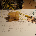
I have been working on the Beach 40 project for a few weeks now and have made some progress but I was having some difficulty with the VXO (variable crystal oscillator) and the LO/Buffer (local oscillator and buffer.) The oscillator section is supposed to generate an RF carrier frequency, in this case close to 7.2 MHz. I wasn’t generating the carrier and I couldn’t figure out why.
I decided to put these sections aside and move on to the next section and ruminate on the problem for a while. The next section in line was the Balanced Mixer / Product Detector but I was missing a component that I was still waiting to arrive, so on to the next stage, the Microphone Amplifier.
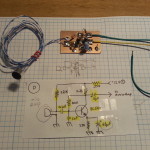
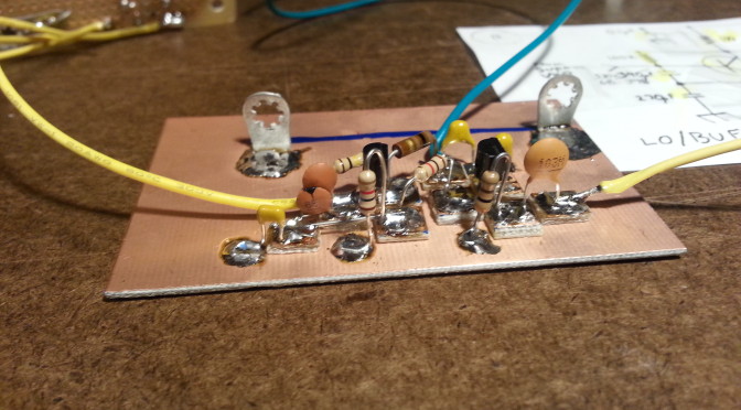
Laying out the parts physical locations on the circuit board I came to the transistor, one I hadn’t worked with before. So I decided to look up the data sheet and be sure of the pin-out. It wasn’t what I was expecting it to be, and then it hit me, like a Log from BLAMO! My oscillator wasn’t oscillating because I had the pinout wrong on the transistors! I finished the Mic Amp and the part arrived for the BM/PD.
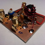
I moved on to the BM/PD and finished it then looked up the transistors on the LO/Buffer and sure enough, I had them in backwards.
With a little coaxing and cajoling, and construction of a really scaled down crystal oscillator for testing, I got them turned around and everything back in place, well sort of. I missed a jumper and had to go back and solder that back down, but the after that the oscillator was oscillating like a good little oscillator should. Oscillation!
With a little tweaking and and the removal of the Fine Tuning circuit that I still haven’t figured out, I am back on track and only three sections shy of a full transceiver. At present I have the sections built for a QRPpp transmitter a very, very, very, very low power transmitter, somewhere around the microwatt range but I should be able to modulate a voice transmission a foot or so to my DC receiver.
The Mic Amp test is actually a test of the VXO, LO/Buffer, Balanced Mixer, and Mic Amp sections and has me transmitting some AF (audio frequency) along with the carrier through the Balanced Mixer to help locate the signal in the band. Once I locate the signal on a separate receiver it’s time to tune out, or “suppress”, the carrier signal on the BM/PD section. I’ll be doing just that in the next few days. Hopefully I will remember to video the test and post the video.
I already checked out the VXO and LO/Buffer when I checked the frequency. I can check the Mic Amp just by hooking it up to a speaker, which I will. Then the BM/PD gets it’s big on-air check out.
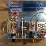
All that’s left to have a working receiver is building the Audio Amplifier which I have already laid out, I just need to solder the parts down and test. After that I need to build the RF Amp to have a transmitter. I will want to also complete the Low Pass Filter before transmitting though. I don’t want to splatter the band or anything.
So the schedule for now looks like a completed Beach 40 transceiver should be on the bench next weekend or there abouts.
That’s all for today.
73,
~Jon KK6GXG

