
Mark I – Transistor Based Oscillator
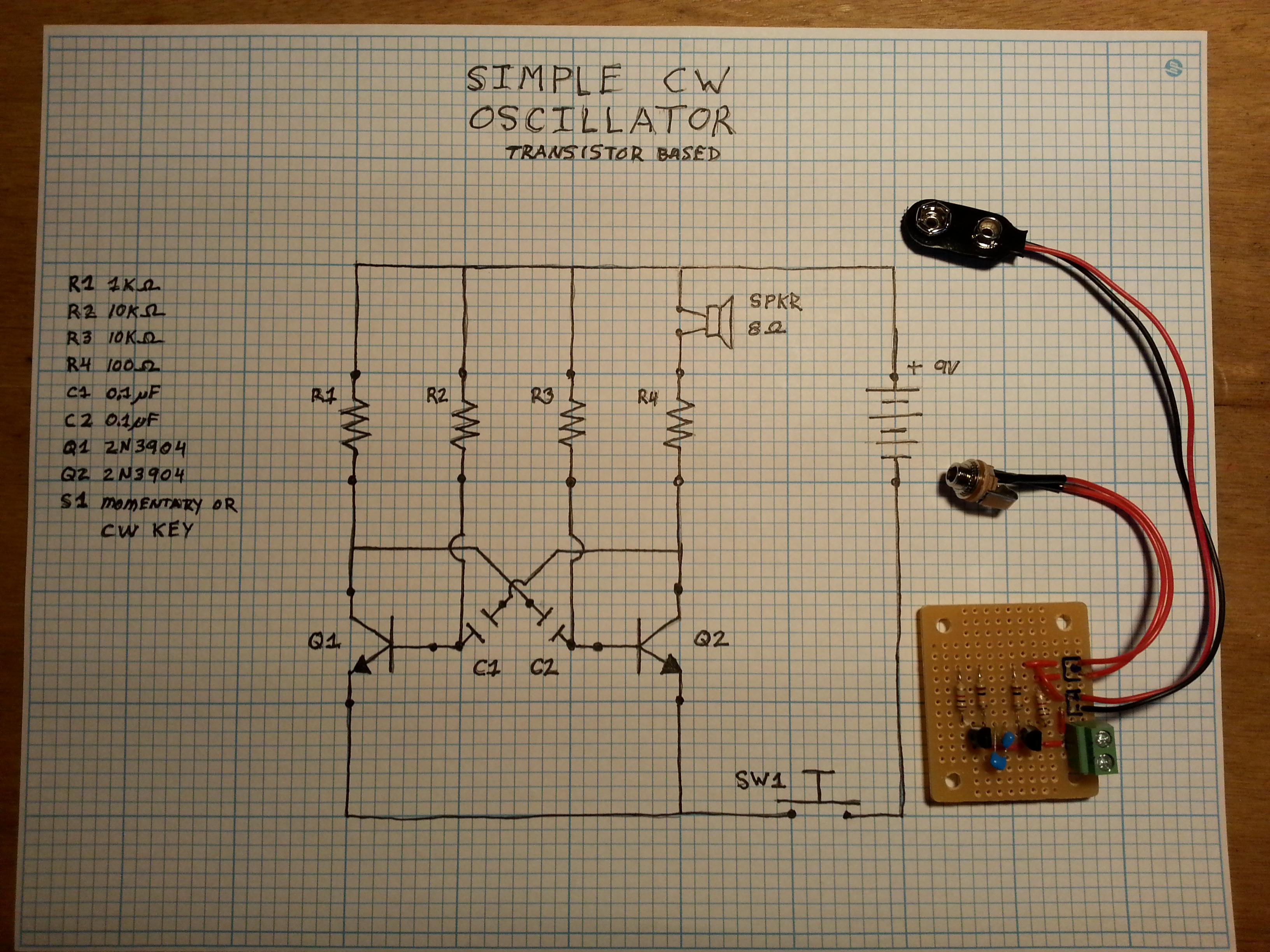
This was the first attempt at an oscillator for practicing CW. I don’t remember where I found this particular schematic but there are a ton of oscillator circuit designs available online. Click here for a Google search that will result in a lot of options (over a half million hits!) The image results are a good place to start.
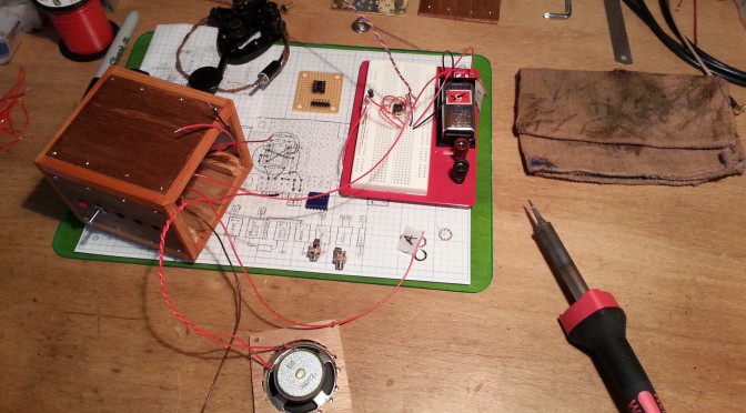
I committed to protoboarding this design because I wanted to play around with it some more. At the time I built it I was planning on getting an O-Scope but I didn’t have one yet. Now that I have one I can revisit the circuit.

The AF (Audio Frequency) tone is unstable to say the least. It varies from 3kHz to about 200Hz . The wave form resembles a square wave, but only loosely. It is very spiky and irregular.
While this is a simple circuit to build, uses only a few components, can be built very inexpensively, was a fun basic electronics project, and would be good as a beginners circuit / soldering project, I wouldn’t plan on using it for much more.
I would avoid it for a CW practice oscillator. If you are serious about learning CW, do it with a stable oscillator that will be pleasant to listen to. This thing can squeal at times.
Mark II – 555 IC Based Oscillator
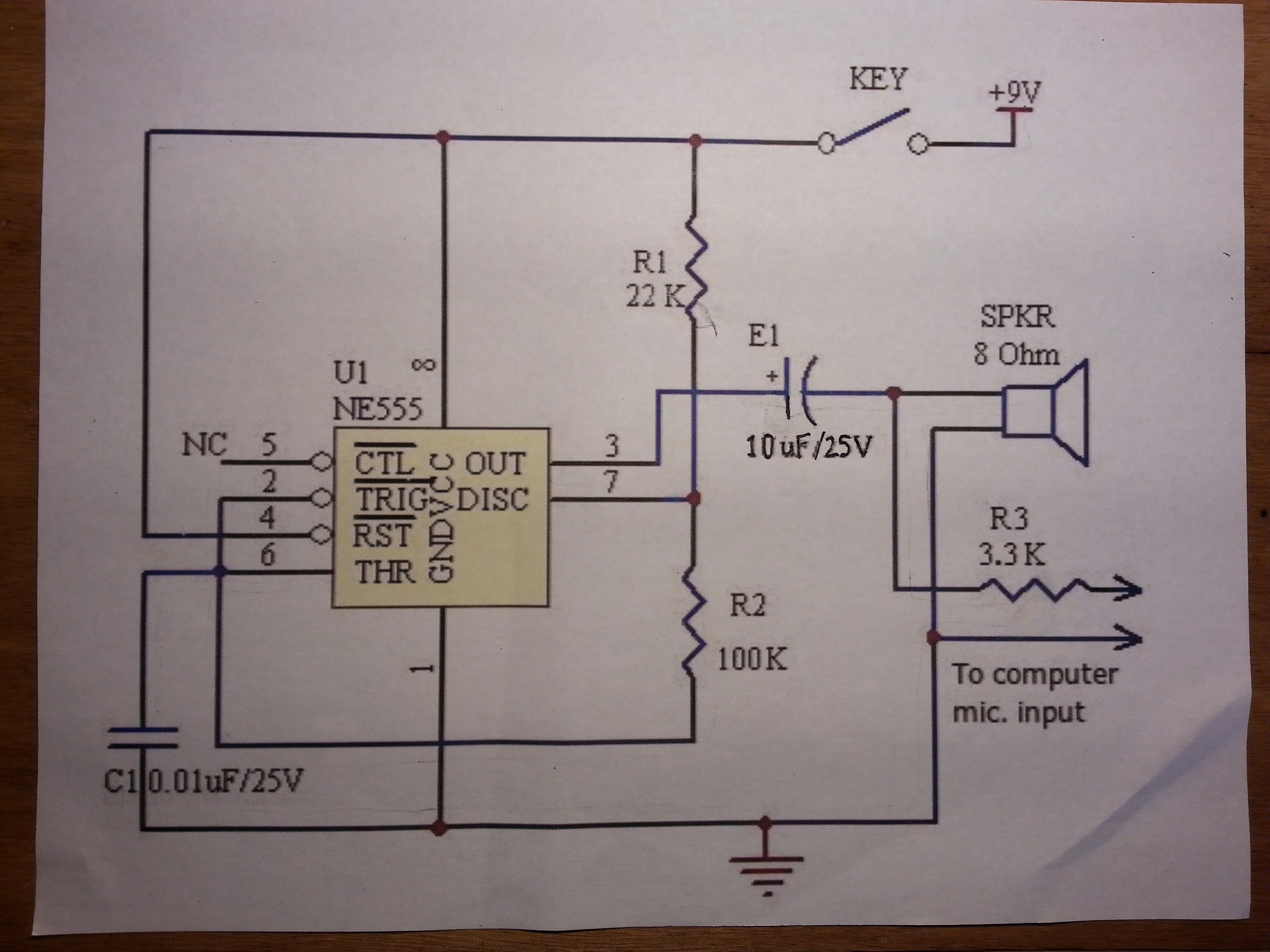
As the section title above says, this oscillator is based on the 555 timer integrated circuit, a much more stable oscillator, also with few parts.
I documented the build on Flickr but the focus was more on the cabinet build and less on the electronics.
This circuit makes a good CW practice oscillator. Still a very easy build for beginners and fun. I was going for a steampunk look with the cabinet build. There are many things I think I would do differently in the cabinet build to make it easier, and smaller, but the oscillator works just fine as is.
The waveform is a pritty clean and produces a consistent 724.8 – 725.2 Hz tone. This circuit does consume more energy then the other. I put a fresh battery in the oscillator, had done a week of cw practice 20 minutes a day when life called and shelved it in May 2014. I just took it down and did some testing when the battery died.
Thing two I might change, a positive power cut off switch to completely lift the battery from the circuit. Just a thought.
Here is a short video of the cabinet and the oscillator in action with a CW key. There is no additional AF amplifier which brings up the one thing I might change. It my be a good idea to add a variable resistor on the output to adjust the volume.