Tag Archives: frequency counter

40 Meter Ceramic Oscillator

The Beach 40 saga continues. My original VXO design, well… it stunk. I’m not sure why, but the best selectivity I could get out of it was only a couple of kilohertz, very annoying.

20151104_161508

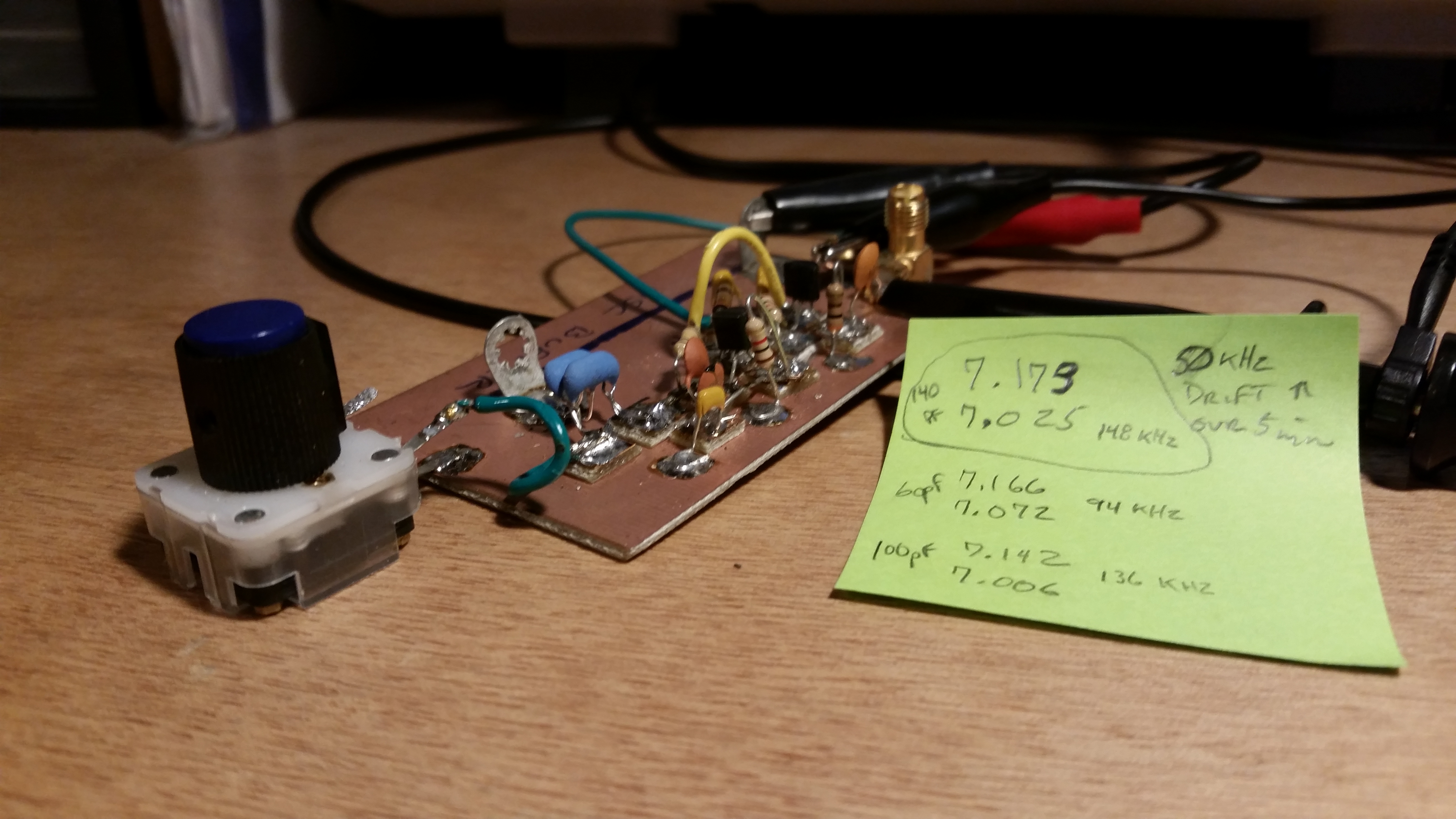
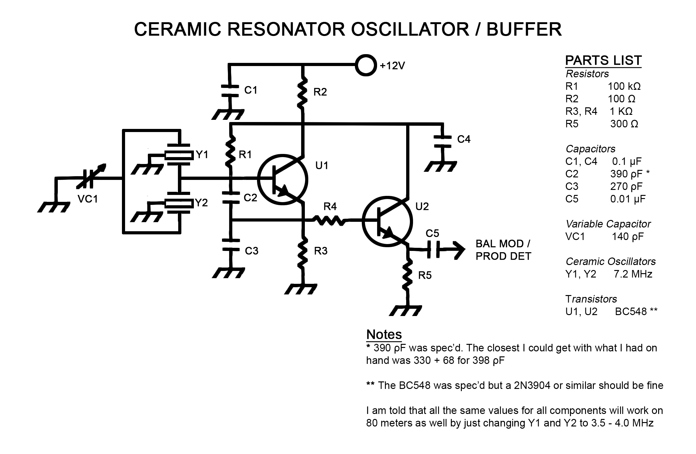
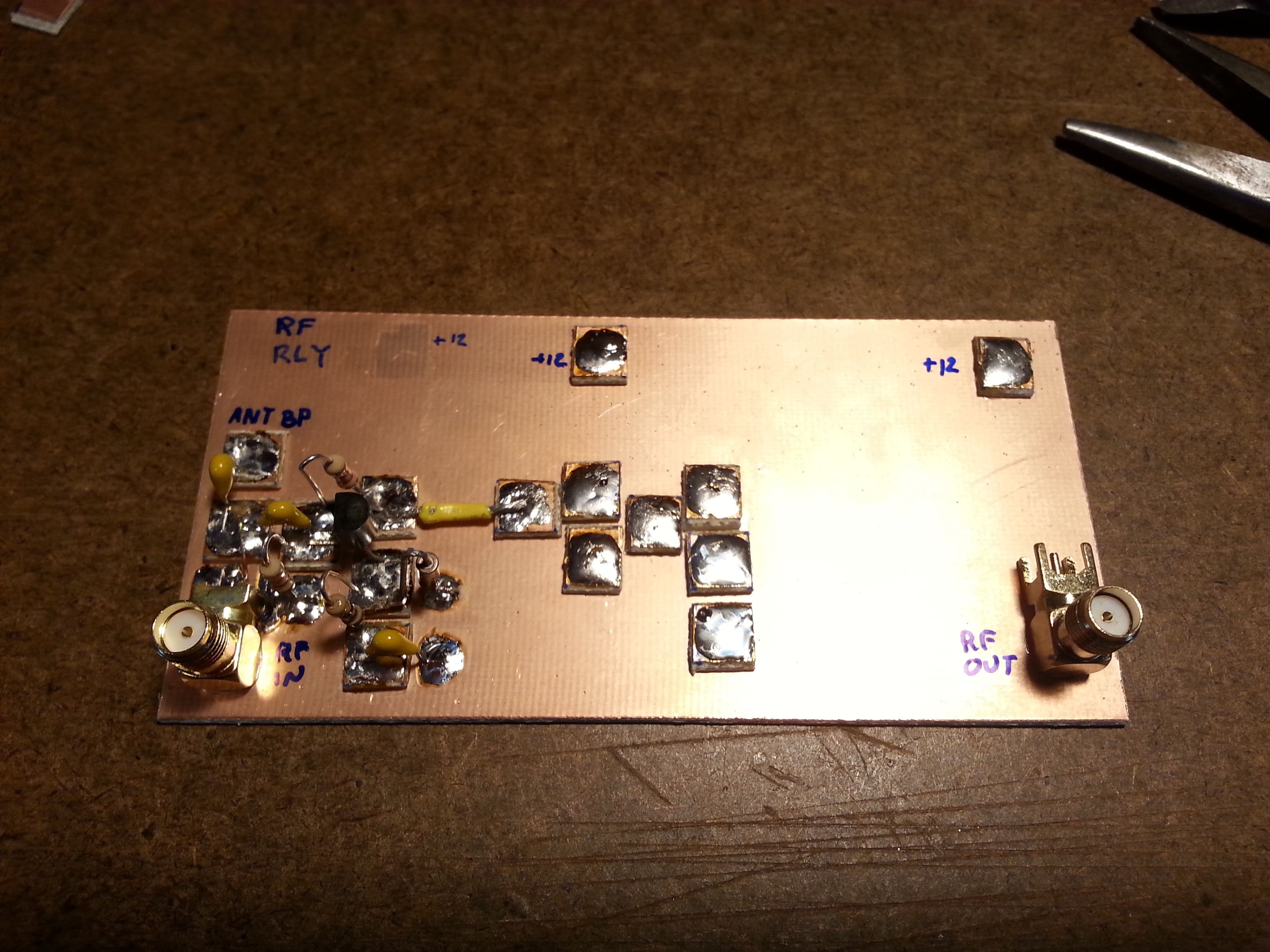
I have been working on a VFO design to get full band selectivity but in the meantime I came into some ceramic oscillators for 7.2 and 3.68 MHz. The best part is that I replaced the entire Super VXO section with a 140ρF variable capacitor and two ceramic resonators.

20151104_161541

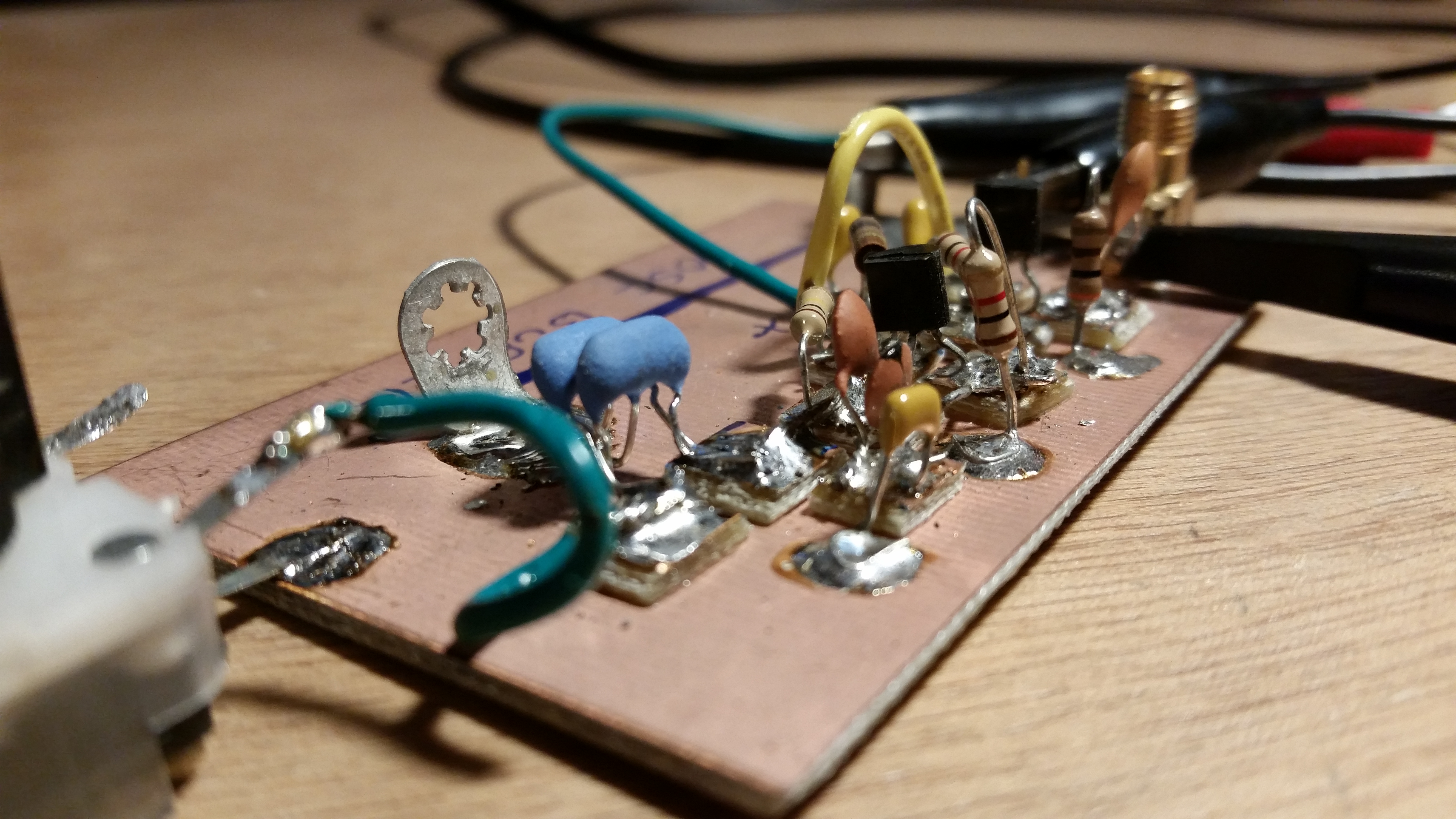
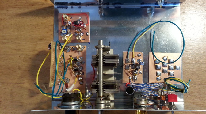
By placing the 140ρF var cap in series with the two paralleled resonators and feeding the output directly into the local oscillator buffer… Ta da! A working  VXO.

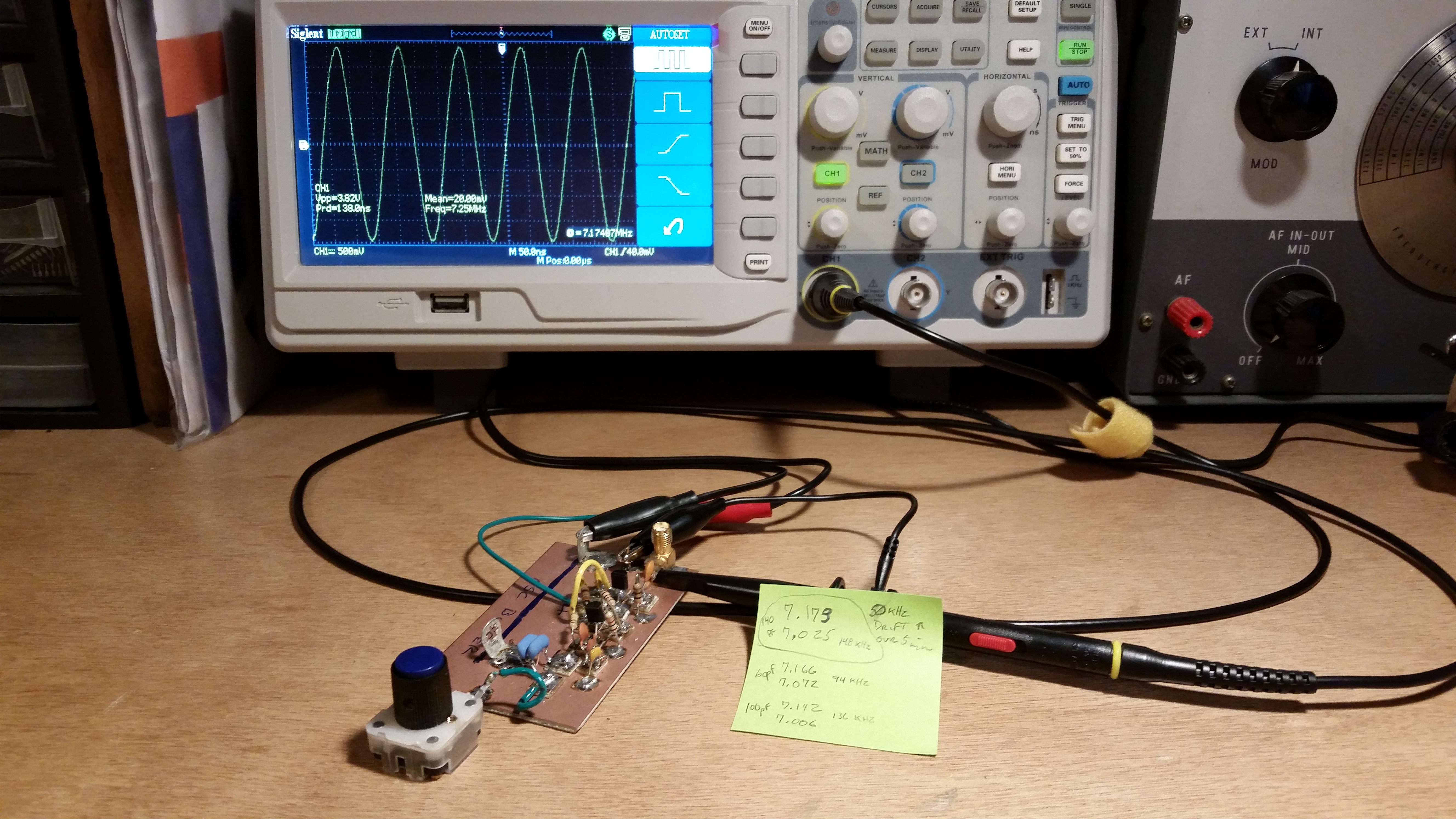
This time, instead of a few kilohertz the VXO pulls a full 148 kHz, from 7.173 MHz down to 7.025 MHz. It is certainly not the full band but it is a useable range. Over a five minute period, I noticed a slow 50 Hz drift that eventually settled out to a point where it continued to float ±10 Hz.

20151104_161453

This is not a final solution, but it will work well enough to get this QRP DSB transceiver on the air for testing.

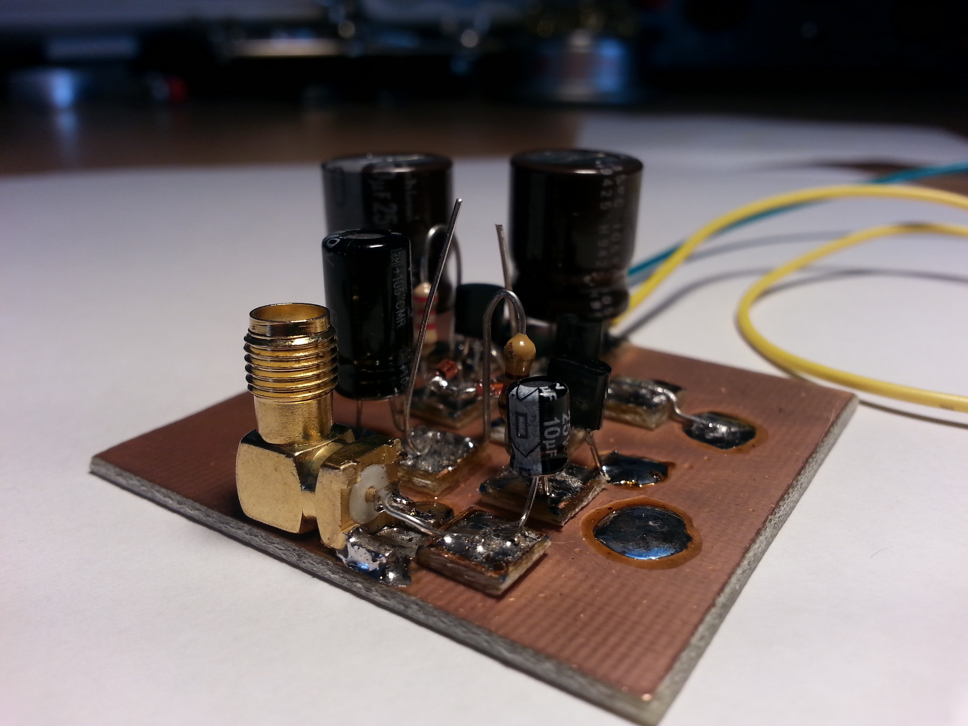
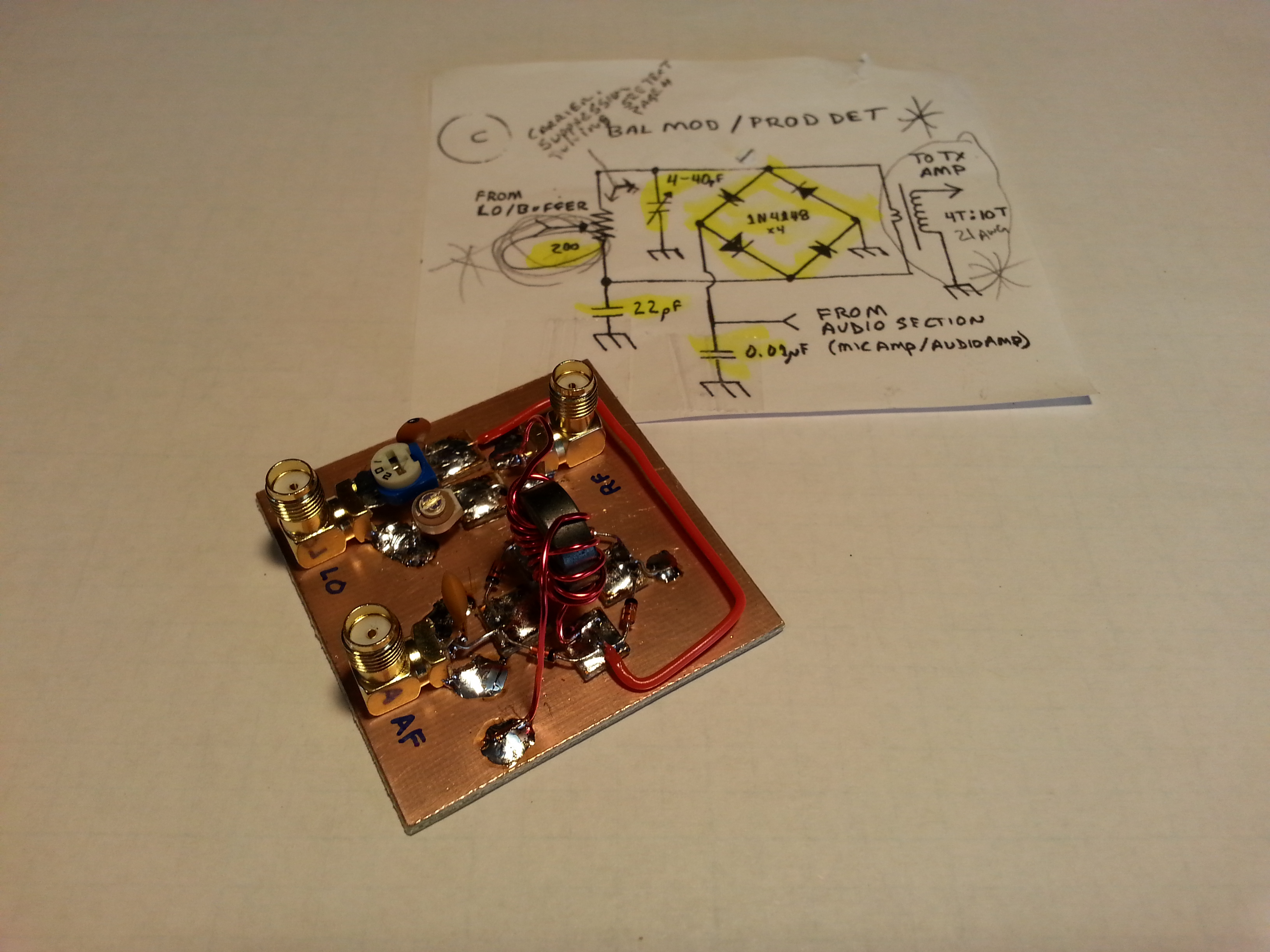
Of course now that I have a working VXO attached to the local oscillator buffer, it’s time to hook it up to the product detector/balanced modulator… success! With the VXO, buffer, product detector chain attached to an antenna it was time for a little listen.

20151104_163742

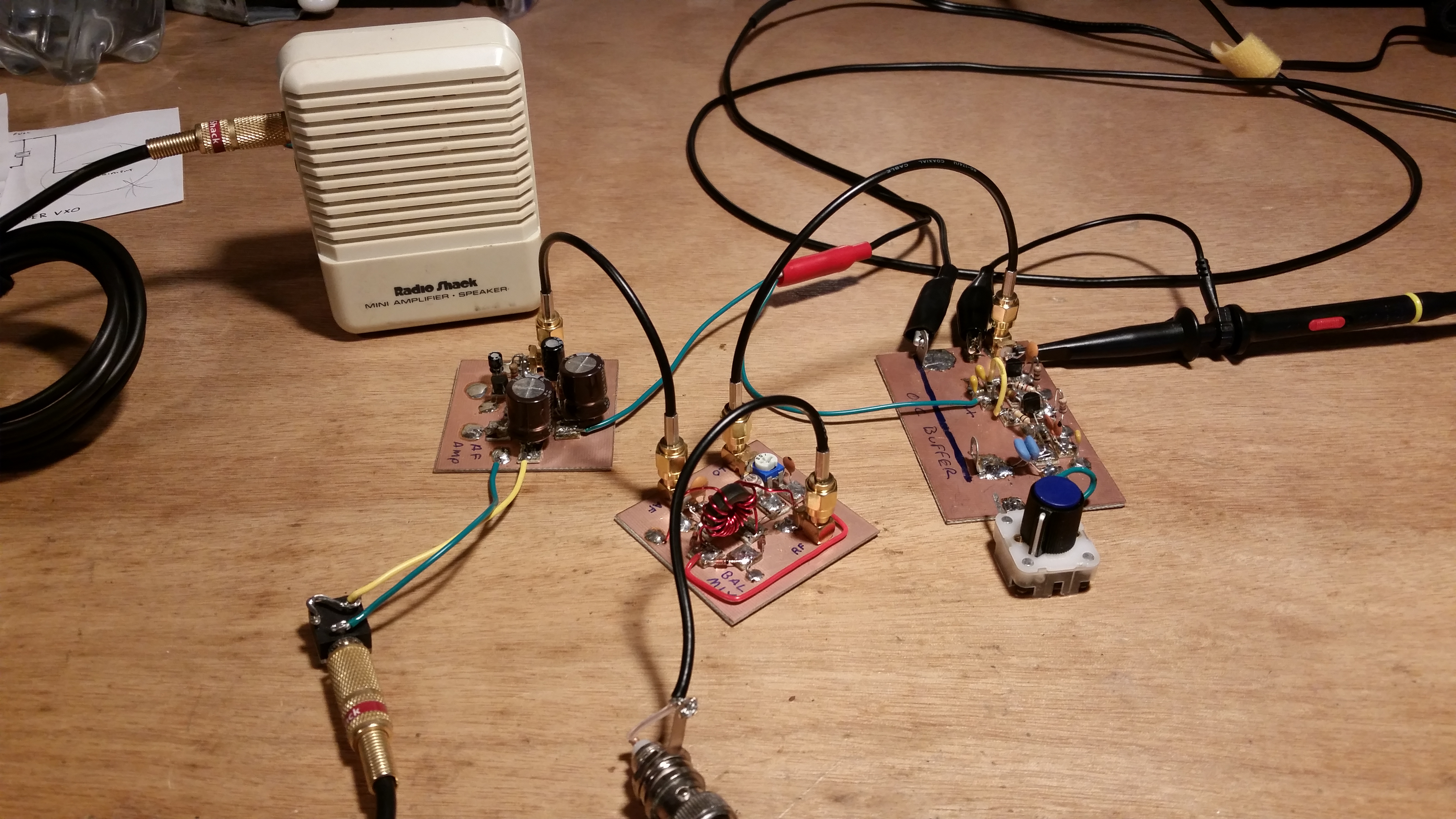
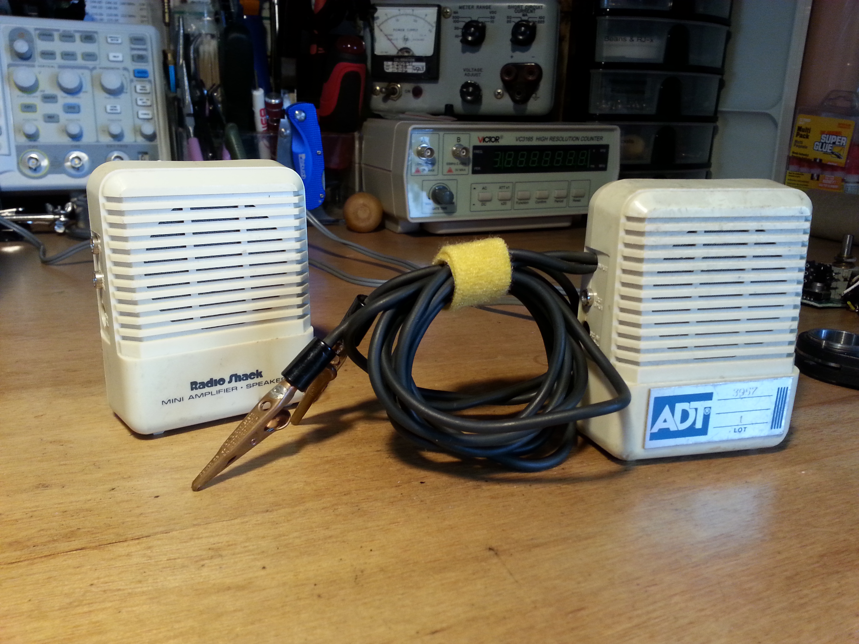
The audio amp still has some issues as far as power drain off when power is disconnected, but it does fine as an amp. I plugged everything together and plugged the audio out into an external amp so I could tune around without headphones.

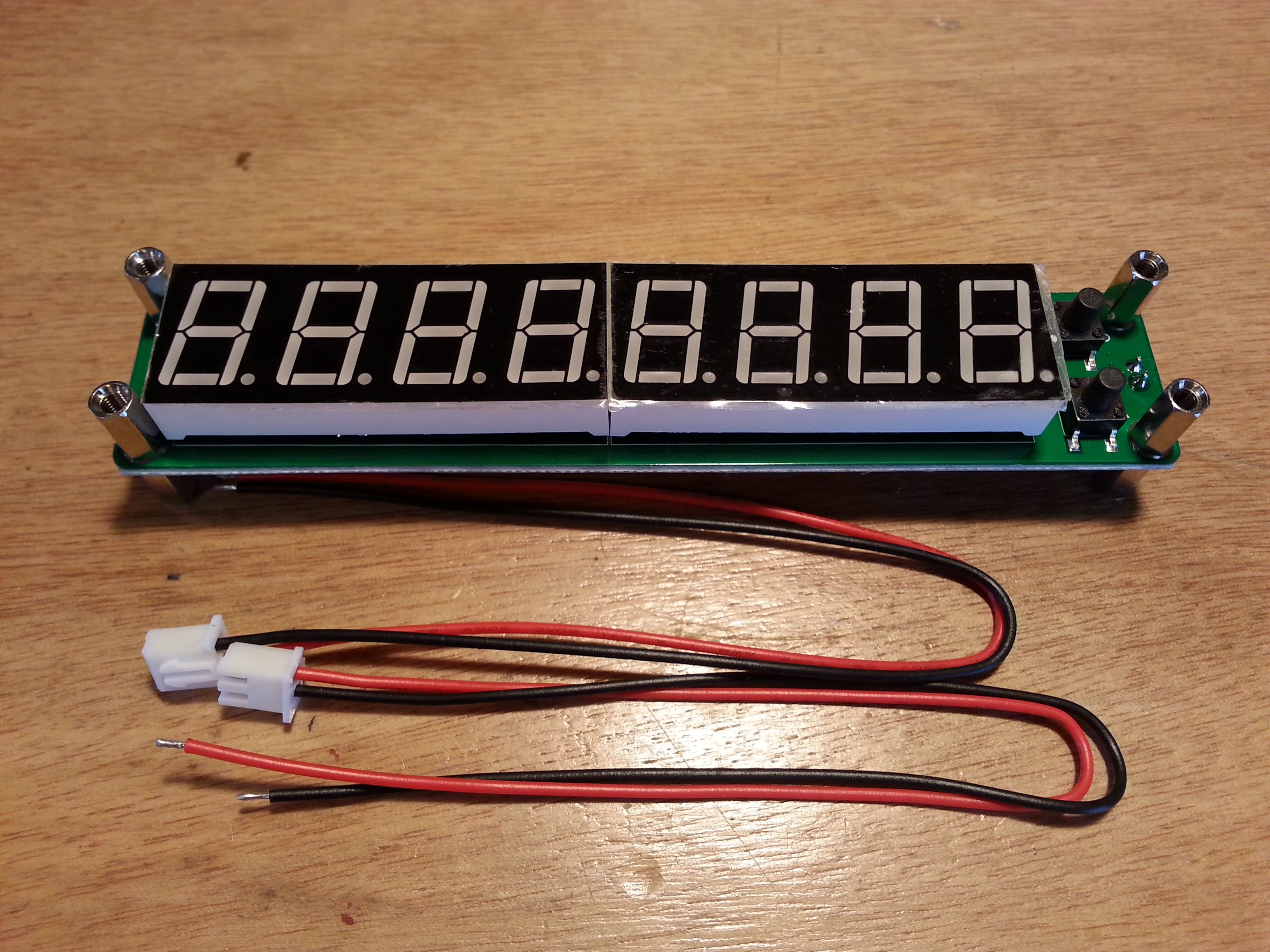
Not much on the band, but my frequency generator with a small antenna plugged into it put out enough RF for the receiver chain of the Beach 40 with the temporary VXO to pick up its 400 Hz signal and cross reference the VXO frequency displayed on the oscilloscope with that of the frequency counter connected to the frequency generator. So one could say I have a working receiver, mostly anyway.

Next up: First and foremost I need to get my documentation in order. In particular, I need to get the schematics in conformance with the actual circuits.  After I get the documentation in place I need to get to work on the audio amp.

After the RX stage is all dandy, my attention will turn to the TX/RX switching. I can’t do anything more with the TX side until I get the TX/RX switching squared away.

Anyway, that’s all for now.

Until next time,
~Jon KK6GXG

UPDATE: As promised, the conformed schematic for the VXO/Buffer section…

Ceramic Resonator VXO

40 Meter DSB Coming Soon

Busy weekend for me.

20150530_161129Before moving on to Beach 40 progress, I got something else in the mail. A frequency counter module I ordered off eBay for ten bucks. I am thinking about using it in a future radio project as a digital frequency display.  Not sure what project, but it beckoned to me and I figured it might work out well.

20150530_221434In a related sidebar, I have been doing some VFO research. I have been looking at several options and one that seems simple and efficient is using varactor diodes to replace the air dielectric capacitors in tuning circuits. I have some ten-turn potentiometers and found a good deal on Motorola 68ρF varactors so I bought a bag of 100.

I found N6QW’s website with some great information including a test circuit for testing the tuning abilities of various diodes and transistors. Definitely more to come on this venture after the DSB project is done.

Now, on with our regularly scheduled program…

20150529_164741In the last post I talked about skipping the Balanced Modulator/Product Detector and moving on to the Audio Amplifier.

I built the Audio Amp and got everything all tied in to the panel mount components.

20150529_165009I still haven’t tested the Audio Amp yet and I am saving that for after I get all of the sections built out.

About the time I finished up the Audio Amp the 200Ω potentiometer I was waiting on showed up. With the parts in hand, I moved on to the BM/PD.

20150527_153801The BM/PD build went well. with no real surprises.  The diode ring ended up being laid out in an actual ring configuration with the RF transformer being mounted right in the middle.

The one thing I don’t like about this layout is the really long lead from one side of the diode ring all the way around to the other side of the board to the potentiometer. I don’t know if I can come up with a better layout in a future rendition but for now it should be fine.

20150530_214234One of the first things I started with today was building the interconnect cables out of RG174 coaxial cable and SMA connectors. I considered MMX connectors since they just push on rather than thread on but they are way expensive. I have seen a number of builders use coax interconnects for modularized construction and it makes separation for experimentation much easier.

20150530_220849One cable I made was actually an antenna, a test antenna at least. For testing transmission sections giving them something to radiate out of. By using a receiver near the transmitting device I should be able to copy the transmission. It’s the one on the right if you hadn’t guessed.

20150531_110751Cables, of any kind,  are one of those things that can seem fairly easy to do, but when they go bad, they can go epicly bad and it can be hard to detect. The only preventative effort I know of is to take your time, use a light touch, don’t force things, and pay attention to detail.

I made 4 interconnects, 1 antenna, and one single end cable for connecting to the antenna outlet. It took a coupe of hours, but all of them are solid mechanically, and test to be solid electrically.

20150530_221209After getting the cables done, I hooked up the antenna and one of the interconnects but I still haven’t done any of testing beyond the Local Oscillator.

I have a lot of testing to do but I’m almost done with the modules so I wanted to plug away and finish up the modules.

20150531_143223The last thing I worked on before turning off the soldering iron was the three stage RF Amplifier.

The pic is the first stage, a buffer stage. I started the board with a configuration in mind but by the time I got to the third stage I had shifted a few things around.

20150531_150232One thing I wanted to point out is the spacing of the stages. In this pic I have most of the second stage done and the pads for the third stage laid down. The gaps between stages are for the addition, if needed, of shielding between the stages. This amp is fairly low power so I don’t think it will need the shielding, But I wanted to make the option available.

20150531_161643The third stage saw several pads moved and things reconfigured a little. The yellow leads are the RX Amp Bypass (short lead) and Amplified RF (long lead) lines going to the relay circuit which after a lot of thought this evening will be replaced with cable ports and the relay section will be moved off this board entirely onto it’s own module.

The other bit on the RF Amp board that still needs work are the two bifilar toroids that still need to be wound and installed. It sounds like a lot of work still to be done, but it is getting very close to First Contact.

Thats all for this post. May the magic smoke remain contained in all your circuits.

73,
~Jon KK6GXG

New-To-Me Signal Generator

120 kc (kHz) to 200 mc (MHz)

On Saturday I picked up a few things at the De Anza Electronics Flea Market. The most impressive acquisition would be the Lafayette Signal Generator for $20.

I have been needing one and I was dreading the prospect of having to build one and having a tough time without the right tools for calibrating it, so this was a great find and a steal of a value, though I didn’t know it for sure until today.

One thing I have learned about buying used electrical/electronic equipment, particularly in at a flea market, is that you have to take your time and open it up, get documentation, inspect and clean the equipment before attempting to use it, or plug it in for that matter.

20150414_075130 Sunday was opening day. I noticed right away that I would need to replace the power cord grommet as it was in two pieces. I didn’t actually get to anything else until today.

Today I inspected all of the wiring and components, looked for hot spots and anything that would indicate an over heat. Having found nothing of the sort I moved on to cleaning, which there was surprisingly little to do. I made sure the tubes were cleaned and had no fingerprints on them. Now that I have a piece of tube equipment I will need to get a tube tester. 😉

With the cleaning done it was time for the plug-in and smoke tests. No pops and and no smoke! I let everything warm up and burn in for a good twenty minutes before starting any tests.

Testing with the oscilloscope began with the AF (audio frequency) side of the generator. After the twenty minute warm up period the “approximately 400 cycles” audio tone as specified in the manual turned out to be stable at 388 cycles (Hertz). I can work with that.

“kc” is kilocycles. The term is essentially the same as the more familiar kilohertz along with “mc” megacycles being the same as megahertz. The change over in terminology occurred slowly from the mid 70s to the mid 80s. Many hams still use kc and mc. I use them interchangeably depending what I am referencing or who I’m talking with. This piece of equipment has frequency labeled on the dial as kc and mc.

20150417_152319Moving on… The generator did its first diagnostics job with a portable amplifier I have had for a very long time (the one on the right). I clipped on the amp to the audio out and it turn out the volume control on the amp is trashed from banging around in my tool bags for a couple of decades so I will need to replace the potentiometer in that this weekend.

I then moved over to the RF (radio frequency) side of the generator and clipped on the oscilloscope. The RF side is divided into 5 switchable bands. I checked each band by referencing the frequency on the dial with the frequency on the O-scope. All five bands checked out very closely to the dial. A little lead or lag here-and-there, but overall pretty close for this equipment and its age which I’m guessing is about as old as me (made in the mid/late 60s).

20150417_152206The frequency counter I purchased last year has been giving me problems. New equipment, cheap (figuratively and cost), and no manual. With the help of the new sig gen and the oscilloscope I managed to fix a couple of minor problems and figure out the modes on the counter in the process. Looks like the electronics bench is finally coming together.

Now that I can check the receivers I build I can also check the transmitters I plan on building. I can also check portions of the radios as the construction moves forward. I plan on building more of my own test equipment but it’s nice to have a reference point or two to calibrate off of.

I also did some diagnostics on the 40 meter direct conversion receiver project and updated the project page… some very interesting results, you should take a look. 🙂

A productive day I think.

73,
~Jon KK6GXG