Tag Archives: QRP tools

Radio Kits

When I first started this blog I planned on posting a separate page for each project I did. After some thinking on the matter I decided that scratch-built projects would have a page dedicated to them.

20150518_213658
L/C Meter IIB from Almost All Digital Electronics AADE.com

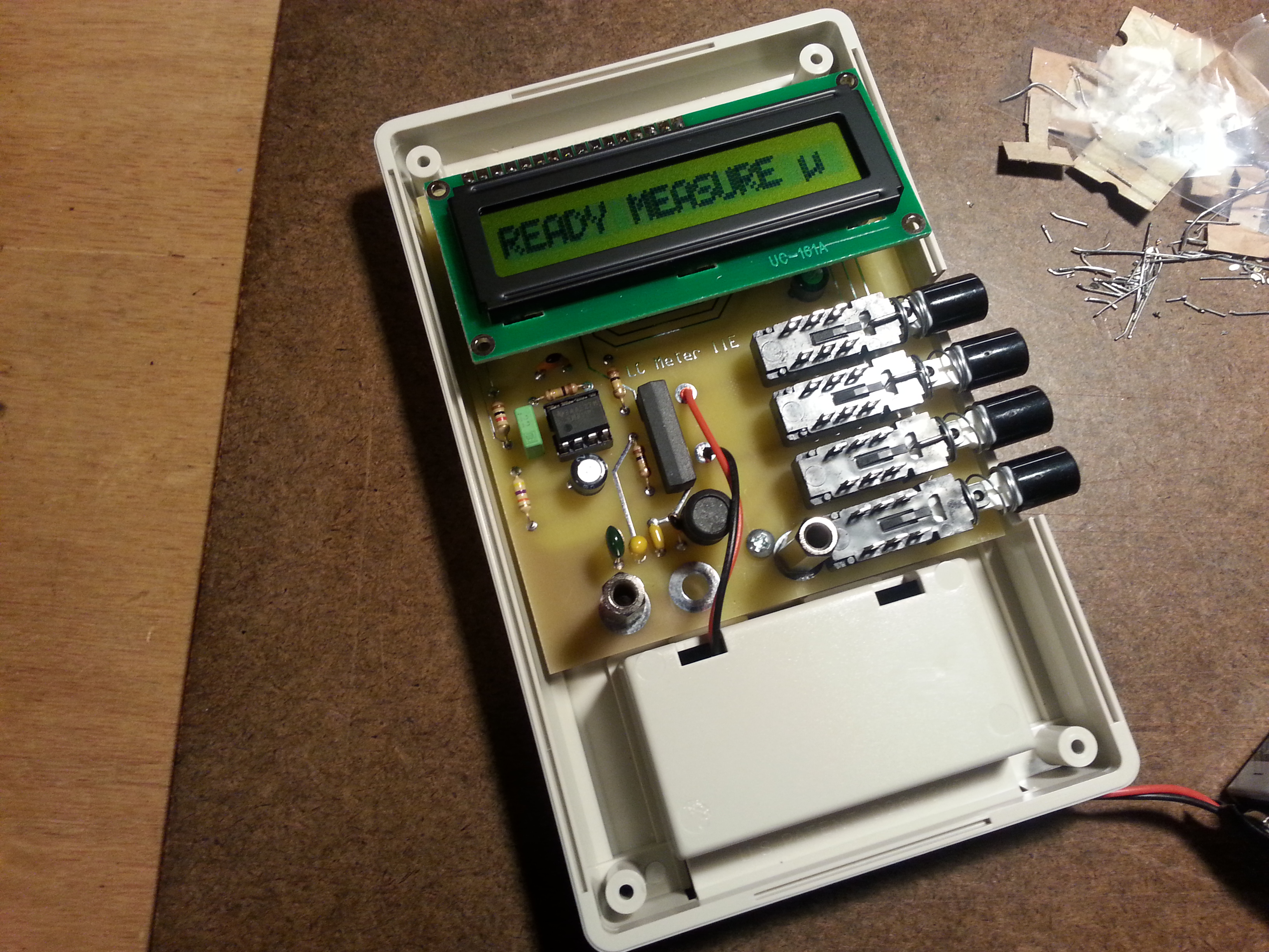
The last post was an example of a project while important and interesting, I don’t think it rated a page. I am of course referring to the post on the AADE L/C Meter IIB.  Part of the reason I’m not devoting a page to the project is that it is a kit, a great kit, but still a kit.

Don’t get me wrong on this, kits can be a really useful tool. Often times kits can cost less that the parts purchased individually. They can also be useful in overcoming sourcing issues.

20150403_090944
Scratch-built, from paper to product

For the beginning builder kits are a great way to get your feet wet and try the building process as well as exercising the construction skills needed in scratch-building. A kit can get you on-the-air faster than scratch-built as well. Kits give a potential scratch-builder a chance to see if they actually like building.

Kits also offer a choice for the builder. The kit can be built by just filling up the board following the instructions, or if you are looking at going scratch-built later on, taking the time to trace things out and compare the schematic with the board layout, and understanding what components perform what function along with how and why things are placed as they are goes a long way in improving your understanding of the circuit.

While kits can be a good learning tool or refresher for the builder, they off-load a lot of the mental gymnastics involved in design, sourcing, layout, placement, and proximity matters. Or at least they should, a poorly designed kit can be a real challenge for even the most skilled builders.

I decided to post about kits rather than page them because of this off-loading. While the kit may be of educational value, it is the mental exercise not the physical work that provides the real educational benefit. I don’t think I would be bringing much to the table beyond the instructions that come with the kit.

Breadboard Radio Kits
4 kits from BreadboardRadio.com waiting to be assembled

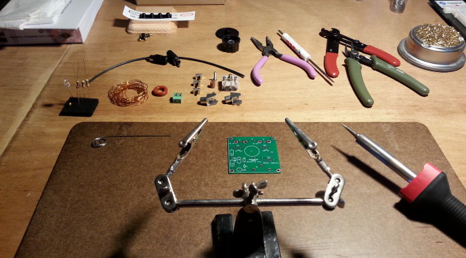
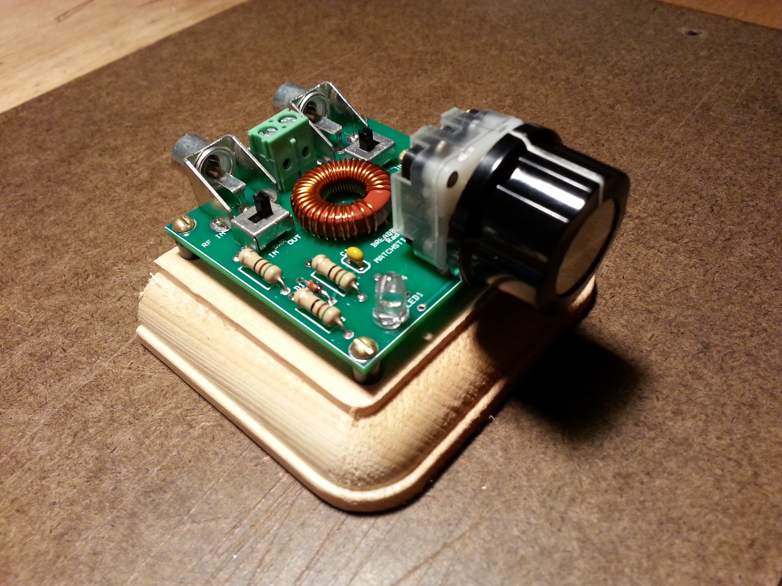
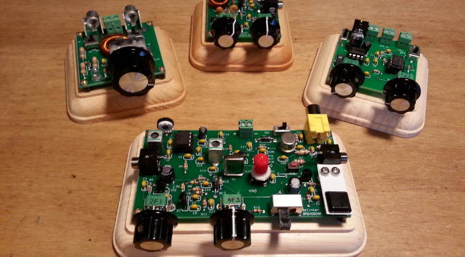
So don’t be surprised when you see a project as a post rather than a page. I will start the trend in my next post when I show off the BreadboardRadio.com kits I built before beginning my 40 meter Direct Conversion receiver. I will likely set up a Kits page as an index to kit projects if it looks like I need one.

Stay tuned and 73,
~Jon KK6GXG

The AADE L/C Meter IIB

If you don’t work with RF electronics the need for an L/C meter may not be readily apparent. If you work with RF, you have likely found capacitors and inductors in the junk pile and played hobb trying to figure out the value, unless of course they were marked.

My first homebrew toroid inductor. Aint she purdy?

If you wind your own inductors or make your own capacitors the need for an L/C meter is a no-brainer. I bought a cheap Chinese manufactured meter and it was no bueno. No redeeming qualities what-so-ever.

Within the Amateure Radio world AADE (Almost All Digital Electronics)  and the L/C Meter IIB has earned an almost legendary reputation for being just the piece of equipment the homebrew ameture needs.

20150518_173544Being a homebrew ameture and a recycler of electronic components, I decided to buy the L/C Meter IIB kit and build it. The kit itself is very straight forward. Assembly is well documented and easy to follow.

I have been generating a lot of solder smoke lately so I may have an advantage here in assembly speed but I went from shipping box to functioning test equipment in about 4 hours.

20150518_194352Starting with full parts inventory I went right into construction. The parts list is only one sheet and it is very detailed. After checking in all of the parts and tagging them to the parts sheet I fired up the soldering iron  and started melting metal. Filling the printed circuit board didn’t take long at all.

Th20150518_212344
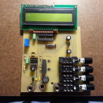
e only hiccough was technician error. I got all of the components soldered in, mounted the board in the back of the case, mounted the LCD, and plugged in the battery. When I turned on the power switch I got nothing. I knew from reading the instructions fancy that that a common oversight is that the contrast pot should be turned fully clockwise. When I went to check the pot I noticed something missing, I forgot to install the IC’s in the sockets. Doh!

20150518_215451
A great product that supports a US, family owned and operated business AADE L/C Meter IIB

After installing the IC’s I checked the pot and Voilà! A working L/C meter.

At $100 a kit that looks as simple as this one does you may be tempted to buy a cheaper factory assembled meter. I would strongly advise against it. A comparable factory manufactured meter will set you back at least twice what the L/C Meter IIB will, probably more.

LC meter
Save yourself the time, trouble, and expense of having to return this piece of junk, don’t buy it in the first place

I purchased a cheap meter for $38, paid $6 for shipping and another $8 to return it. Sure, it looks nice but it is complete garbage.

And if you need something else to push you over the fence on this purchasing decision, buying from AADE supports a family run US business that takes pride in the work they do. Now that’s a bargain at any price.

Solder smoke is filling the air as I continue work on the 40 meter Beach 40 DSB transceiver so check the build page for updates. I will be making an update tomorrow!

73 for now,
~Jon KK6GXG

CW Practice Oscillator

Mark I – Transistor Based Oscillator

Mark I protoboard and schematic

(2015-04-03 This page has been copied to projects)

This was the first attempt at an oscillator for practicing CW. I don’t remember where I found this particular schematic but there are a ton of oscillator circuit designs available online.  Click here for a Google search that will result in a lot of options (over a half million hits!) The image results are a good place to start.

I committed to protoboarding this design because I wanted to play around with it some more. At the time I built it I was planning on getting an O-Scope but I didn’t have one yet.  Now that I have one I can revisit the circuit.

Mark I Oscillator - simple to build and only a few components. Not real stable though.
Mark I Oscillator – simple to build and only a few components. Not real stable though.

The AF (Audio Frequency) tone is unstable to say the least. It varies from 3kHz to about 200Hz . The wave form resembles a square wave, but only loosely.  It is very spiky and irregular.

While this is a simple circuit to build, uses only a few components, can be built very inexpensively, was a fun basic electronics project, and would be good as a beginners circuit / soldering project, I wouldn’t plan on using it for much more.

I would avoid it for a CW practice oscillator. If you are serious about learning CW, do it with a stable oscillator that will be pleasant to listen to. This thing can squeal at times.

Mark II – 555 IC Based Oscillator

The 555 IC oscillator is much more stable than the transistor based one

As the section title above says, this oscillator is based on the 555 timer integrated circuit, a much more stable oscillator, also with few parts.

I documented the build on Flickr but the focus was more on the cabinet build and less on the electronics.

This circuit makes a good CW practice oscillator. Still a very easy build for beginners and fun. I was going for a steampunk look with the cabinet build. There are many things I think I would do differently in the cabinet build to make it easier, and smaller, but the oscillator works just fine as is.

The waveform is a pritty clean and produces a consistent 724.8 – 725.2 Hz tone. This circuit does consume more energy then the other. I put a fresh battery in the oscillator, had done a week of cw practice 20 minutes a day when life called and shelved it in May 2014. I just took it down and did some testing when the battery died.

Thing two I might change, a positive power cut off switch to completely lift the battery from the circuit. Just a thought.

Here is a short video of the cabinet and the oscillator in action with a CW key. There is no additional AF amplifier which brings up the one thing I might change. It my be a good idea to add a variable resistor on the output to adjust the volume.

https://www.youtube.com/watch?v=3yoo2oZG714

BreadboardRadio Kits

Breadboard Radio KitsOn Wednesday I received some awesome mail, the kits I ordered from BreadboardRadio.com arrived! As I am inclined to do, I opened things up and began organizing and inventorying the contents there in. Counter to the habits of a younger Jon, I printed all of the distructions, what I tend call them, and read them all, cover-to-cover. Even before setting up the first project!

I completed the electronics of the Matchstick antenna tuner Wednesday evening. Without a receiver or transmitter I couldn’t do much with it. Yesterday I finished the electronics of the Sawdust regenerative receiver and proceeded to spend over four hours tuning up and down the 40 meter band.

There was some broadcast, not sure if it was AM bleed or SW though I am leaning towards SW, phone (voice), and some digital transmissions. I believe I heard both RTTY (Teletype) and PSK31 (ASCII keyboard-to-keyboard). No CW though. I was really hoping for some Morse Code. Lots of band noise. The solar storm this week is making for some interesting sounds.

Progress shots were taken and will be uploaded to the usual places, here, G+, and Flickr, but I wanted to get them all wrapped up nice and purdy first. Because they are kits and will be done over the weekend most likely, I figured it was worth the wait. I am going to post about each kit separately though.

When I said a kit was completed, I deviated from the distructions in one respect. They called for finishing the wood bases before the electronics so the mounting of said electronics goes directly onto a clean, freshly finished mounting. Well, I didn’t do that.

Matchstick antenna tuner kit from BreadboardRadio.com

I wanted to finish all of the bases at the same time… and, okay, I wanted to get a radio on the air ASAP. So, yes I will finish the bases, but it will be all at once. I I am not sure with what finish I will be using so for now the kits get mounted on the raw base.

Before the kits arrived I built a simple ½  λ dipole to have something to test the radios with, and it does work, but I don’t like the feed point or the wire spools. I didn’t take any pictures because, well I’m not particularly proud of it. That may sound vane, and it is, but some hack jobs just shouldn’t have pictorial evidence.

To resolve the antenna issues and to address the bases for the the kits I think a little fabricating shop time is in order. This morning I am designing the feed point / spools and after day-job stuff I will look at finishing materials for the kits.

73,

~Jon KK6GXG

50 Ohm 5 Watt dummy load

I have been wanting to build a ham receiver and transmitter for some time but hadn’t found the right project, well now I have. A low power (2-5 watts) in the 40 meter band (7 – 7.3 MHz) for CW (Morse code.)

One of my reasons for this choice is its a good quality radio with tuning of the full 40 meter band and no crystals. I also need to get cracking on learning CW so this seemed to fit right in.

Anyway, I want to get started on the receiver next month so I am working on a few tools to work with and test the radio project as it moves forward.

I have five tools to build, all of them are relatively easy to build and don’t have many parts they are a Peak-peak RF probe, an RMS RF probe, an RF sniffer, a 50 Ohm 5 Watt dummy load, and an RF power meter. Today I built the 50 Ohm 5 Watt dummy load.

The dummy load is the black cylinder attached by a very short coaxial cable and connector. The guts of the load are twenty 1,000 ohm 1/4 watt resistors all connected together in parallel. One end of the resistor ribbon is connected to the shielding of the cable and the other end to the core wire. Then the whole thing is rolled up into a cylinder.

The roll of resistors is covered by a sleeve of heat shrink to insulate it from the copper casing made from two 1/2″ pipe caps and a short piece of pipe. With the resistor bundle insulated I put a small zip-tie as a strain relief on the cable. Then the copper tubing and caps are closed up and another piece of heat shrink is put over the whole thing holding it all together.

I futzed around for a while to make a cylindrical cage for the resistors and just wasn’t working out. The only reason I wanted to do it that way was to make in look a little classier… on the inside… anyway, now it is all done and works great. I can now test low power radios, up to 5 watts, without an antenna or transmitting spurious signals or doing damage to the radio. Yay!

50 ohm 5 watt dummy load