
Back on the radar!
As of March 2023, the Beach 40 is back on my radar after a long hiatus. There will be some changes to the project scope and methodology in its resurrection but everything will be detailed here on the project page so stay tuned 🙂 there is more to come on this project.
This project is my implementation of VK3YE’s Beach 40 design. I will be updating this project page as the construction progresses.
Over the last few weeks, I have been tweaking things here and there. My original project concept was for a simple design using only discrete components. While I have stuck to the discrete components edict, I did complicate things a little.

A mod of the VXO that Peter advocated on his site was the addition of a fine-tuning circuit to the basic VXO. Also the use of dual crystal segments for stability and additional frequency range. The inclusion of switchable crystal pairs was also suggested. I expanded the Super VXO by using a 7 pole selector switch and diagramed 5 crystal pairs.

My implementation of the super VXO uses a resonating inductor for each pair of crystals rather than a single resonating coil for all of the pairs. The idea behind this is that I may get better stability and possibly more tuning range. I plan on building a VXO board with sockets for the crystals and the coils which should allow multiple configurations for testing and comparison.
Right now I only have 7.2 MHz crystal pairs, which is fine for DSB and I will keep testing within the 40-meter band. I do plan on ordering some more crystal pairs once things are up and running.
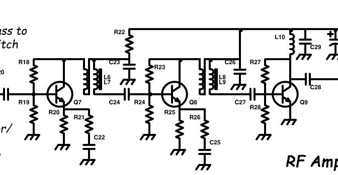
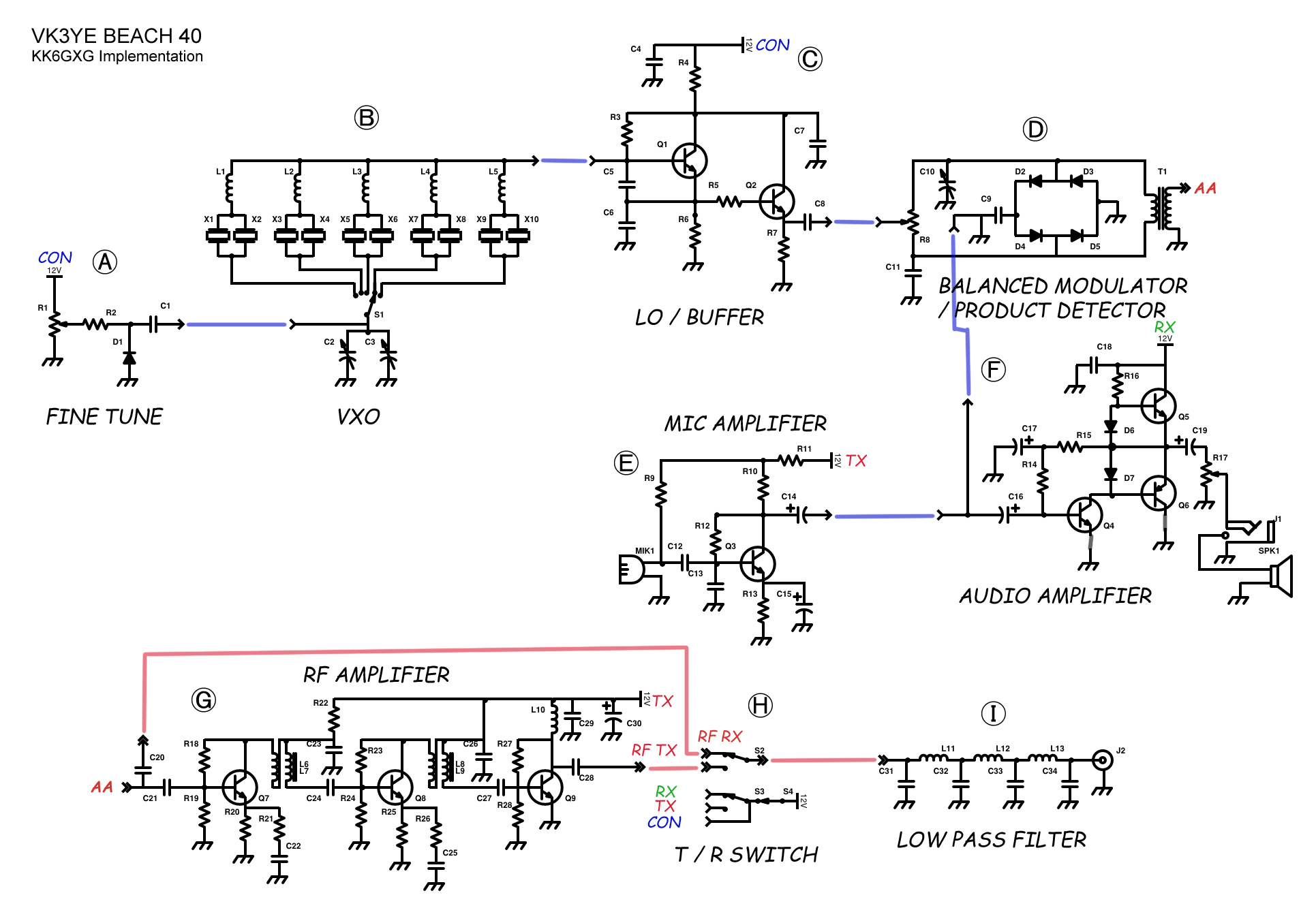
Here is the full diagram. Updates to come.
2015-05-23
This update covers the last week or so. I am just getting to posting stuff on the site.
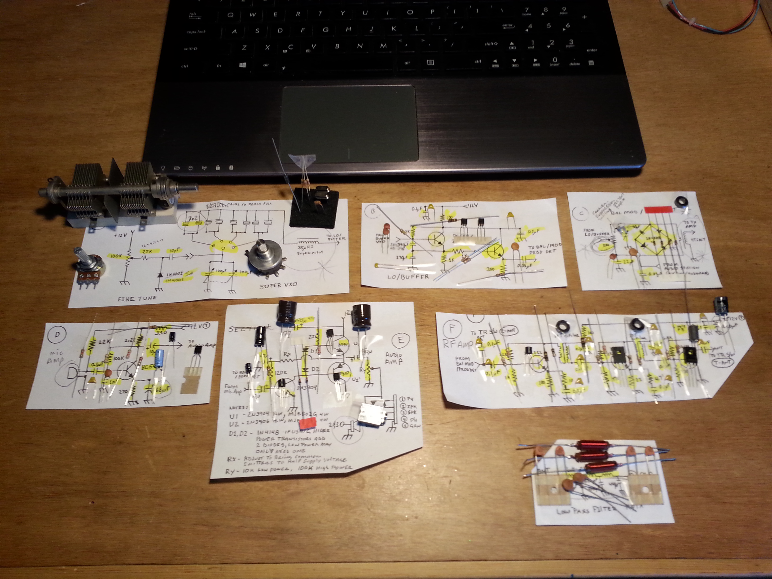
First on the agenda was to kit out all of the sub-sections of the radio. I had nearly all of the parts at this point so I moved on to the building the first sub-section, the Super VXO.
I decided to mount the SVXO and Fine Tune sections on a perfboard then vertically mount the perfboard onto the LO/Buffer section.
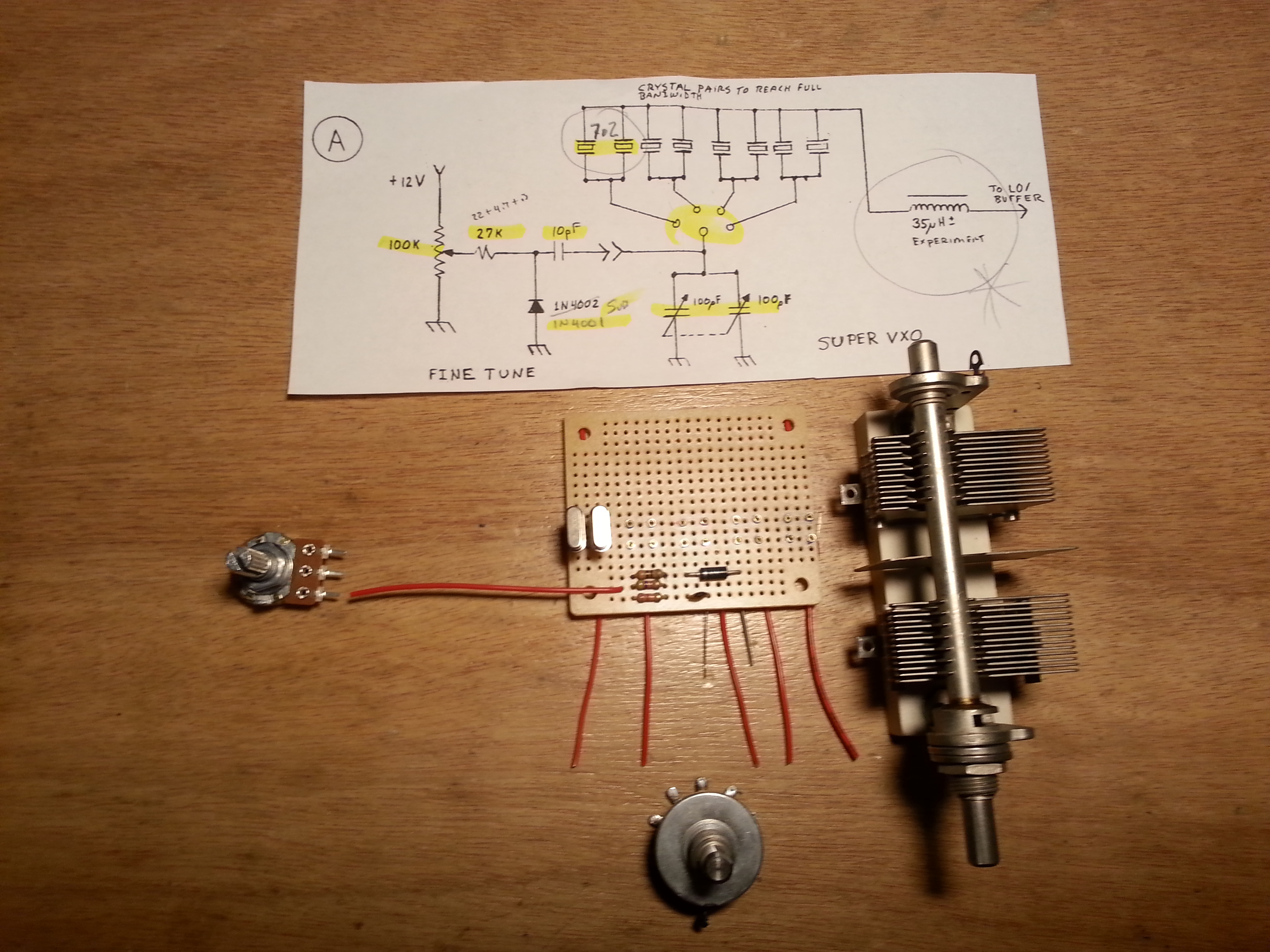
The Super VXO section is pretty straight forward as far as the circuit goes. Due to all the panel-mounted components, it is making the layout a little weird. I need to come up with some wiring interconnects between panel-mounts and the boards, but in the meantime, I will solder wire as needed.
It also became obvious I was going to need mounting surfaces for the panel components before going too much further.
With the test-bed case done I needed to get the individual sections PCB’s cut and ready to go as well as the Manhattan pads.
To get there I had to layout the sub-section boards within the confines of the case. After doing a scale drawing of the case and the panel-mounts positions, I laid out the boards to get the sizes. With the sizes figured out, I cut them from a 12″ x 12″ single-side board.
With the case and PCBs all ready I started building out the perfboard. Next, I had to mount it to the LO/Buffer board.
This is where an L/C meter comes in handy. I needed to make the inductor for the crystal tuning circuit. The documentation called for an inductor somewhere between 20 and 35 μH, the one I built after some trial and error is ≈33 μH. A good place to start I think.
To make the vertical mount I soldered two ground lug tabs to the LO/Buffer board after bending them to 90° from the perfboard with the Super VXO and Fine Tune circuits.

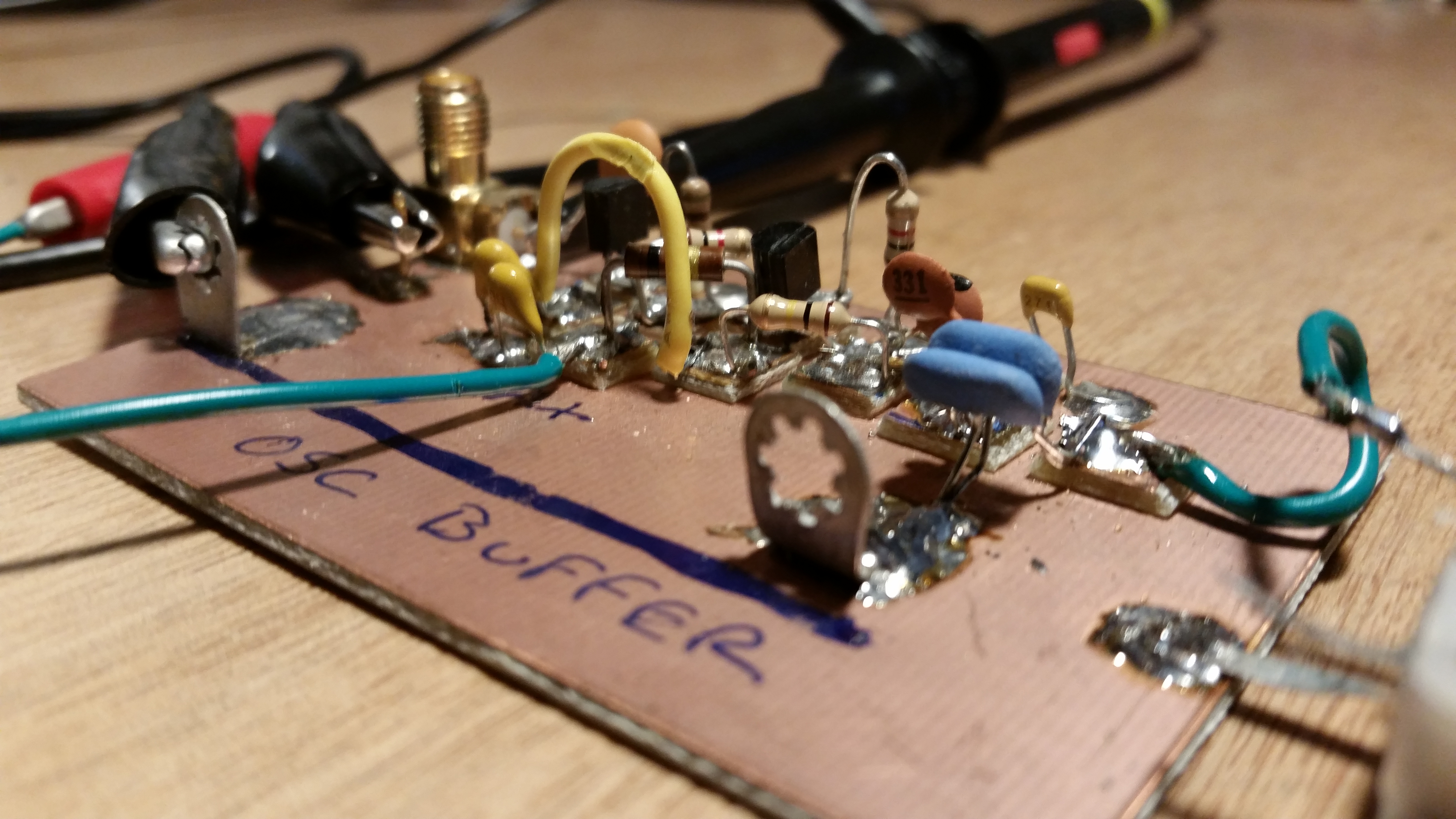
With the vertical mount done and the perfboard populated I built out the LO/Buffer subsection.
This was my first time using the Manhattan style of construction and it worked out pretty well if I do say so myself. It helps a lot if the pads are tinned well before trying to mount a component. With the pad tinned when you apply the soldering iron the solder goes liquid and the part lead just melds in making things go smoothly.
For now, all of the panel-mounts are wired loosely and soldered to the board. I will clean this up when I get to the testing phases.
Before I can do any meaningful testing I need to build and connect the Balanced Modulator/Product Detector. This is where I run into my first slow down, I need a 200Ω potentiometer. I have some on order but they are on a slow boat from China, nearly literally.
Since the next sections can be tested independently and will be used in testing the previous sections I may jump ahead and build the Mic Amp and Audio Amp sections next.

As usual, things don’t always go as planned. I did build the Mic amp next and it went together seemingly without a hitch. I will come back to this later, but it seems to be working fine.
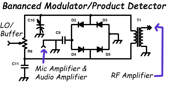
Just about the time I finished it, the 200Ω pots showed up allowing me to go back and build the Balanced Modulator / Product Detector.
Again this sub-section seemed to go together smoothly. The toroidal transformer was a bit of a challenge. Not in the winding as you might suspect, but in the placement on the board. The transformer is increasing the modulated signal so the larger secondary takes the AF modulated RF signal and sends it to the RF Amplifier.
The smaller primary winding is attached across the middle of the diode ring, the balanced modulator, so it makes sense to mount it over the diode ring, the problem is the longer secondary ends towards the top of the toroid. One leg has to come all the way down to the ground and the other goes halfway across the board to the RF connection to the RF amp.
Upon reflection, I could have laid it down horizontally and still left access room to the diode ring while shortening the secondary leads quite a bit. Info for next time.
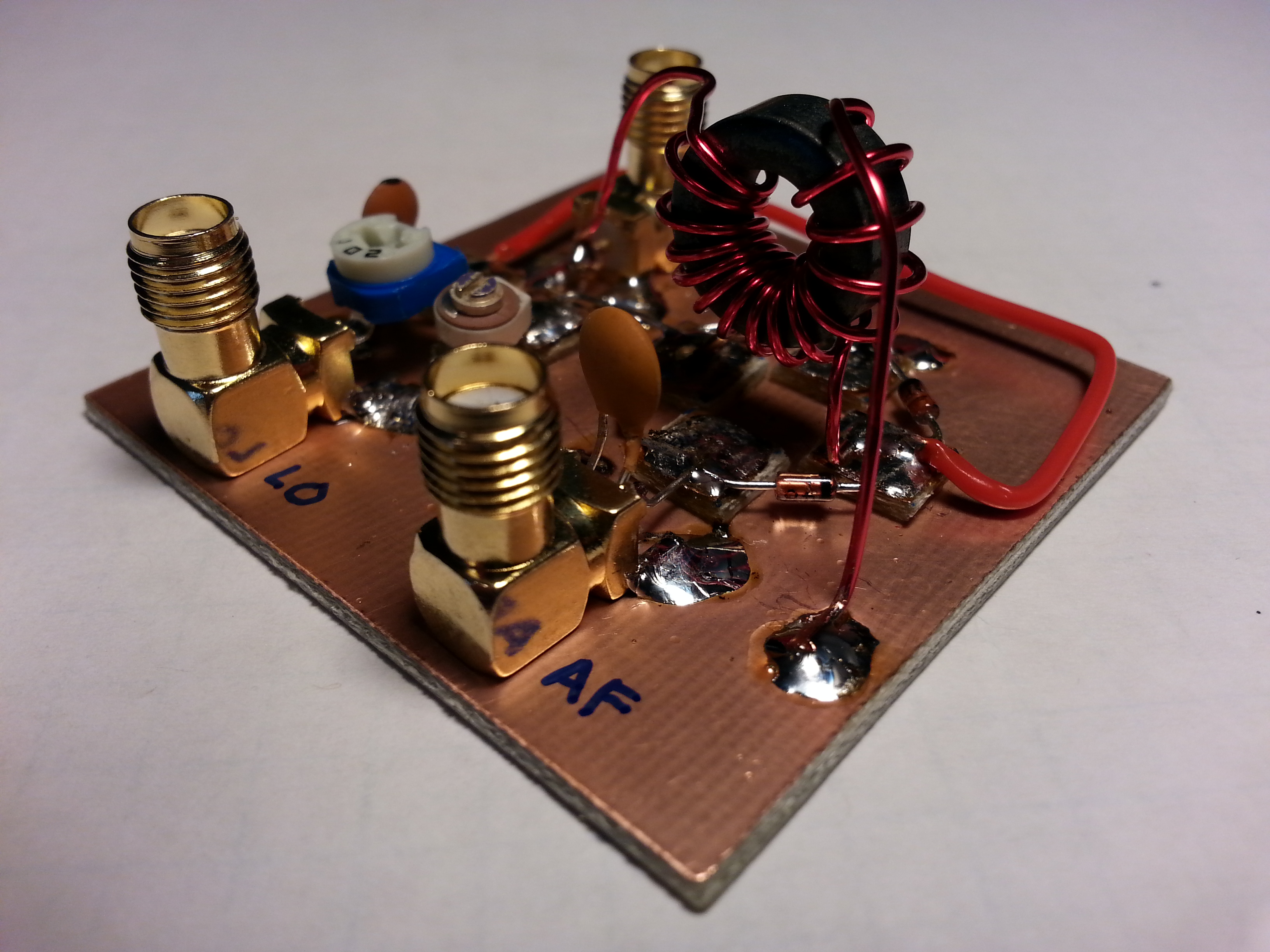
The AF Amp. Well, here is where things went a little awry. More on this in a moment. Audio does pass signals through this amp, though not very amplified. If I connect an external AF amplifier I can hear audio. I decided to plug away and continue building for now since there are only a couple of sub-sections left to build.

RF Amps have a reputation for being a pain. While the basic construction seemed to go fine, I did run into some problems with a short somewhere that appeared after installing the T/R relay. I will need to come back to this as well.
The picture shows the RF Amp before the bifilar toroids were wound and installed. I built the base of the amp and then moved on to the Low Pass Filter.
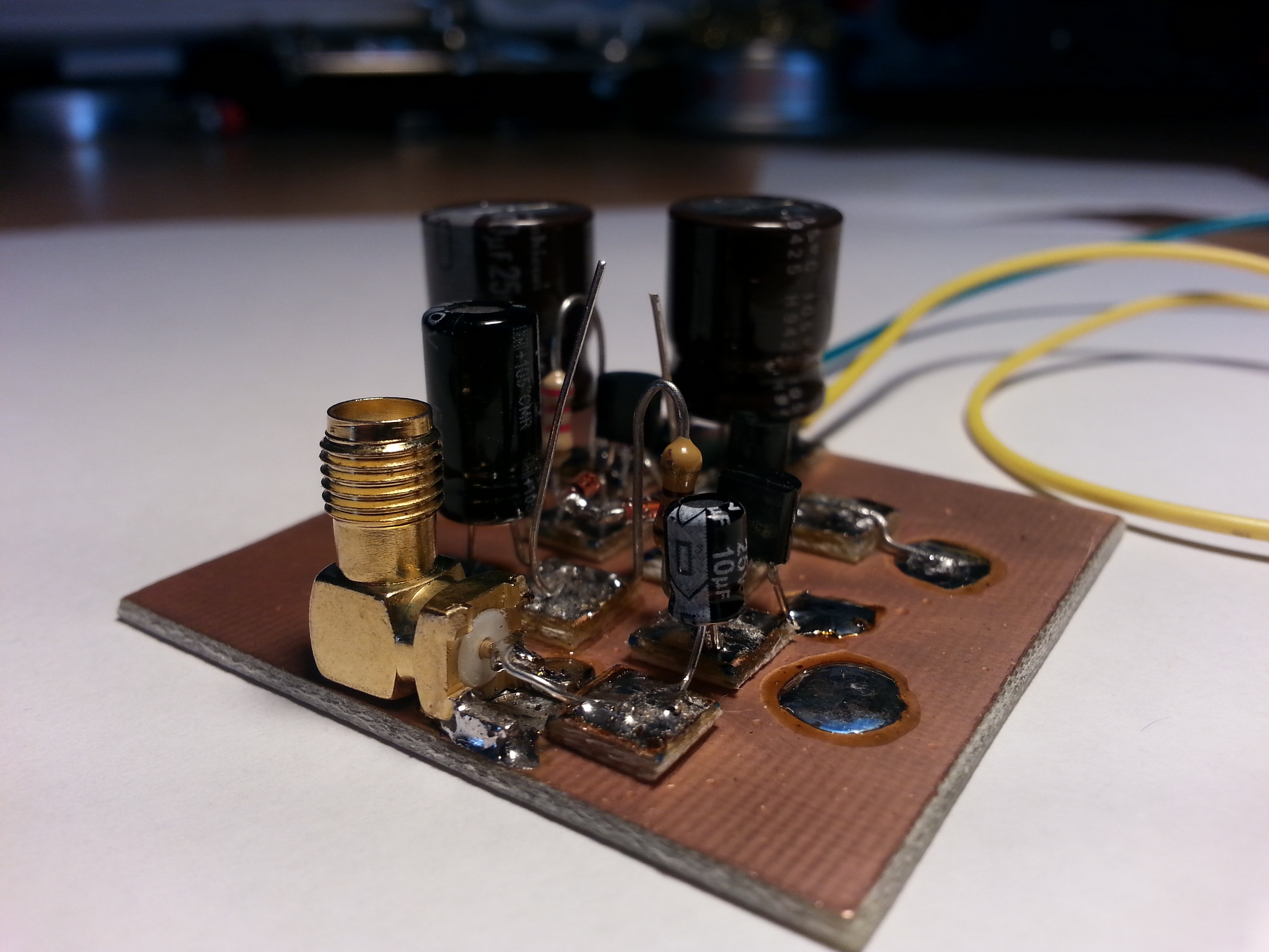
The Low Pass Filter went together quickly and after connecting the receiving sections together allowed the unit to function as a receiver with noticeable attenuation of some noise.
Once I finished the bifilar toroids for the RF Amp and installed a relay for T/R switching the RF path to ether bypass the RF Amp or go through it.
I tied the power for the relay to the power for the RF amp. I don’t know if this caused the low power issue or no but something is taking the power from 12 volts down to about 2 volts.
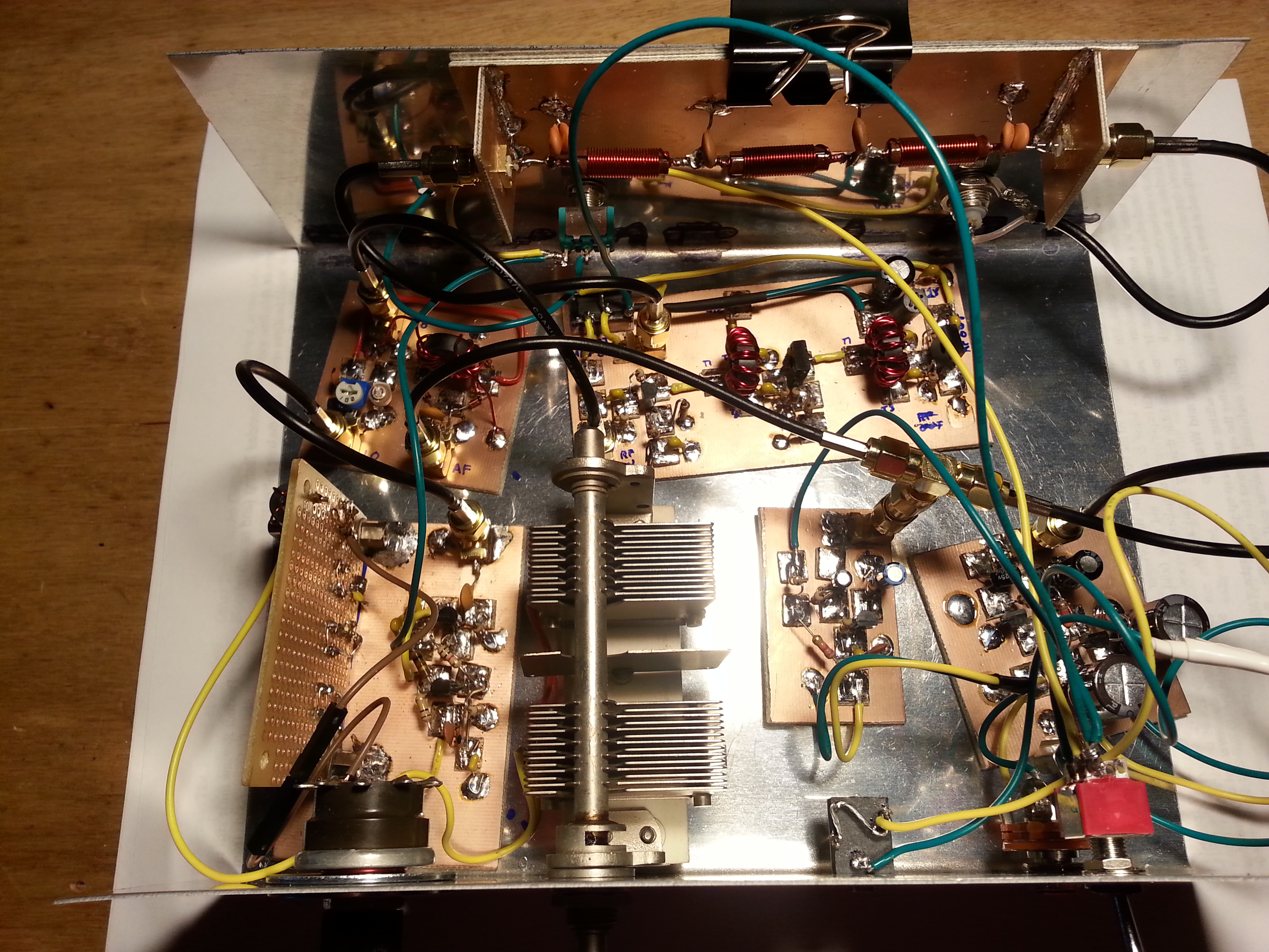
Now that I have all of the sections completed, here is what works:
The VXO/LO/Buffer does generate a signal, the Balanced Modulator / Product Detector does detect incoming voice signals and appears to modulate AF/RF, the Mic Amp does take mic input and amplify it, the Audio Amplifier does take AF signals and amplify them, just not very well, and the Low Pass Filter does appear to be functioning as designed.
What is not working or working poorly:
VXO – Not happy with the selectivity. 100 kHz is not a tuning range, its bandwidth. I need to get more selectivity out f this unit. Because it is a performance and not function issue this moves to the bottom of the fix-it pile.
Audio Amp – Two problems, first the amp stays active for several second after switching power to TX. When the Mic Amp has a mic plugged in it I get a very sharp feedback squeal. Second, the power of the amp is very low requiring an external amp for a speaker or for the headphones.
RF Amp – Currently only able to determine one problem, a dramatic reduction of power, 12 V down to only 2 V on the power connection. Without power, I can’t really tell if there are any other problems. I believe the issue is with the T/R switching relay.
Antenna T/R Switching – I’m fairly certain the power problem on the RF Amp is due to the relay but I will need to dig into that to be sure and come up with a fix. This will be fixed along with, or will be the fix for the RF Amp.
The first order of business is to deal with the Audio Amp. With this fixed I will have a working receiver, then I can go back and work on the transmitter sections.
Another matter that needs attending to is the diagram situation. It has come to my attention that at least one error crept into the schematic images attached to this page has an error, The Balanced Modulator diagram shows a direct to ground from the audio input, the C9 capacitor should be between the ground and the input line.
I swapped over to Linux this month and found some great software for schematics, but I just haven’t had the time to make up new drawings for the Beach 40. Rest assured I will be doing all new drawings and checking them thoroughly, but that may bee a while yet.
2015/11/04
Today I worked on the VXO. I have been working on a fancy-schmancy VFO. I have the design all put together with a 6-section precision power supply and a 5-section VCO. I haven’t started building yet, but I will be soon, now that I have all of the components.
In the meantime, I picked up some ceramic resonators and it turns out, they make a pretty good VXO. After all of the problems I was having with the crystal/inductor oscillator it was almost anticlimactic to have the ceramic resonator VXO work with only three discrete components; two 7.2MHz resonators and a 140ρF variable capacitor.
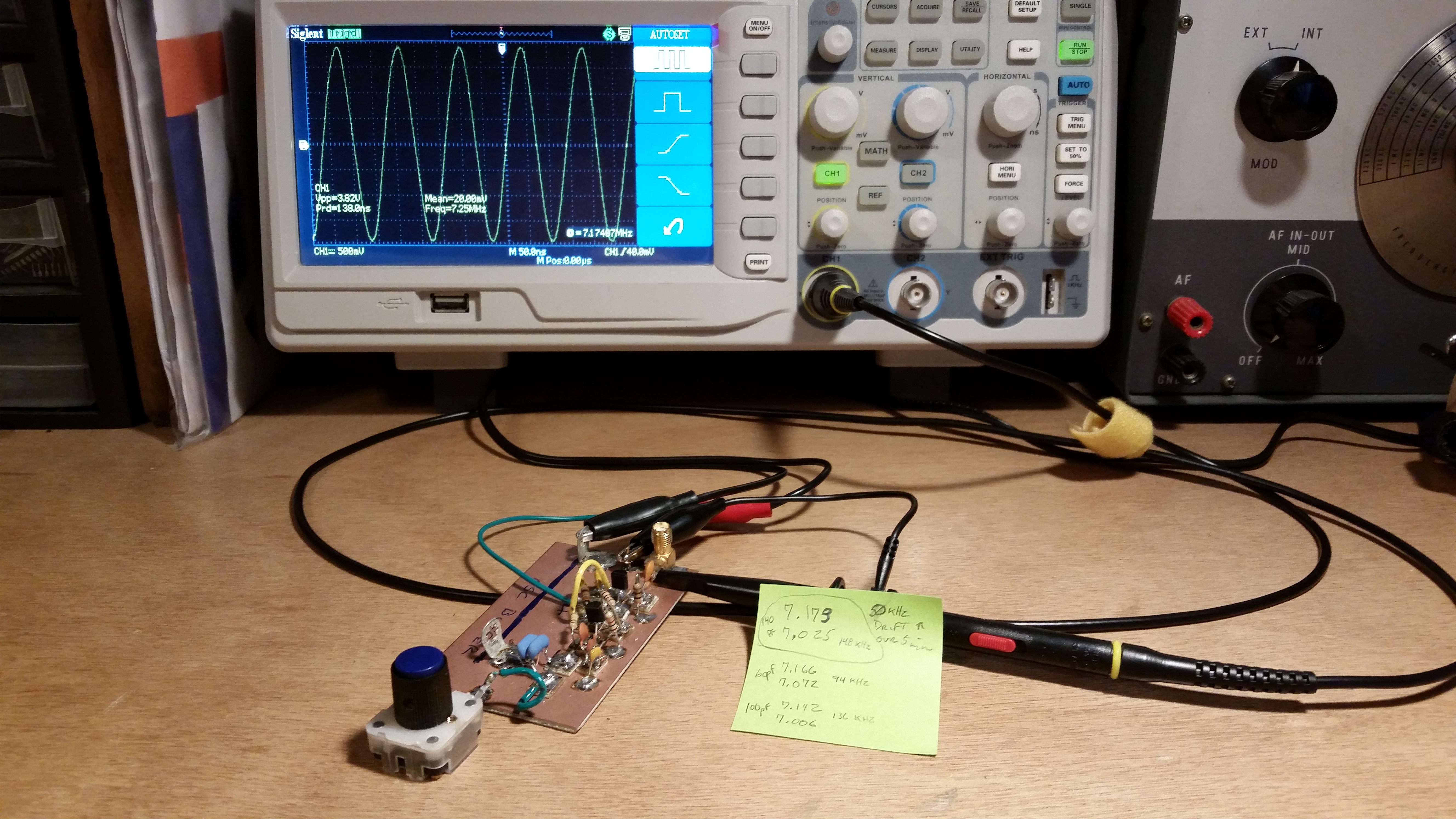
It really was as simple as grounding to the var cap and the var cap in series with the two paralleled resonators, in series into the buffer. Very simple and clean. The selectivity is also better with a 148 kHz tuning range.
Bench and operation testing worked nicely. I still need to conform the schematics but I will post them once I have them done. I wrote a blog post on this VXO as well. It is here.
Until next time, 73,
~Jon KK6GXG