Tag Archives: frequency generator

The BitX 20 & More

The BitX

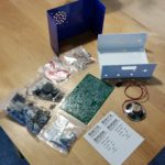
20160618_120709I was fortunate to recently have been gifted a BitX 20 kit by a friend and fellow VE. The kit came from QRPkits.com some time ago, I believe at least a year or so ago.

My intention was to build it for Field Day 2016. Sadly, while I was well on track to getting the radio built, 2 parts were missing from the kit. BS170 N-Channel MOSFETs to be specific. This put on the breaks for the final assembly and stopped me dead in my tracks with the finish line in sight.
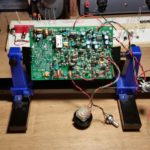
20160624_193754I have the parts waiting for me at Jameco will-call for Monday. Once I get them home, populating the remainder of the circuit board should take about an hour. Then its on to the initial tuning and getting the radio packaged up in its housing.

I will do a full project write-up in the Projects section soon, but for now just an update.

A Homebrew Signal Generator/Oscillator
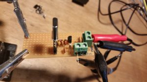
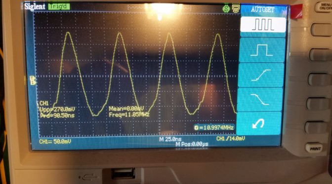
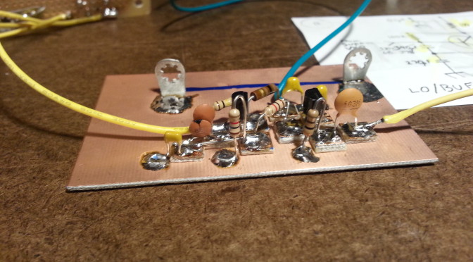
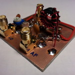
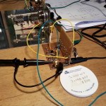
20160622_084953During the BitX build I ran into a small hiccough. The testing at some point calls for the injection of an 11 MHz signal. I would normally use my Lafayette signal generator but for some reason it’s on the fritz so I had to come up with another solution… build an 11 MHz signal generator.
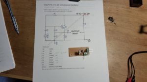
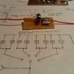
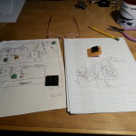
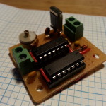
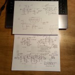
20160622_085219With the crystals in the kit it was easy to build a simple generator with parts on hand and while I only had 1 of the five crystals installed it was easy. By the next testing phase I had installed the remaining 4 crystals. Now I need one for the homebrew SigGen! (click the image for the circuit diagram)

Off to HSC Electronic Supply for some 11 MHz crystals.

This project will also get a write-up in the Projects section soon. This one in in particular has a lot of use in checking unmarked crystals as long as they are between 1 and 20 MHz and is a great foundation piece for beginning builders.

A Homebrew TNC
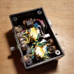
20160524_145401Before I got started on the BitX I was working on getting my Baofeng 2m/70cm HT on digital. I found a couple of designs for a homebrew TNC and set out to make that work.

Because of the way the PTT key works on the Baofeng I haven’t been able to make the TNC work with the HT but it should work fine with my 40 meter QRPme.com Splinter II and the BitX 20.

A full write-up post is coming on this one too.

Look for all three of these in the Projects section for full details on the builds coming soon.

It’s been a long time since I posted, and most of that time I have been working on non-radio stuff. Now that I am back in the swing of things I have more time for radio stuff so I should be able to post more, and make updates to the Projects pages

As soon as the BitX 20 is up and running I plan on getting the Lafayette working again and get back to the Beach 40 DSB. Another Field Day has slipped through my fingers. I don’t plan on that happening again!

That’s all for now folks, 72, 73, and good night!

~Jon KK6GXG


RTFM aka Read The Datasheet

A lot going on these days. Lets start with something educational… No, don’t run away… it’s not that bad.

RTFM or Read The Freaking Manual is directed in this case to datasheets for semiconductors. And this is where we begin our lesson for today.

20150527_113247
The VXO dismounted from the LO/Buffer for testing

I have been working on the Beach 40 project for a few weeks now and have made some progress but I was having some difficulty with the VXO (variable crystal oscillator) and the LO/Buffer (local oscillator and buffer.) The oscillator section is supposed to generate an RF carrier frequency, in this case close to 7.2 MHz. I wasn’t generating the carrier and I couldn’t figure out why.

I decided to put these sections aside and move on to the next section and ruminate on the problem for a while. The next section in line was the Balanced Mixer / Product Detector but I was missing a component that I was still waiting to arrive, so on to the next stage, the Microphone Amplifier.

20150525_135559
The Mic Amp has the mic element temporarily direct wired for testing

Laying out the parts physical locations on the circuit board I came to the transistor, one I hadn’t worked with before. So I decided to look up the data sheet and be sure of the pin-out. It wasn’t what I was expecting it to be, and then it hit me, like a Log from BLAMO! My oscillator wasn’t oscillating because I had the pinout wrong on the transistors! I finished the Mic Amp and the part arrived for the BM/PD.

20150527_154019
The Balanced Mixer/ Product Detector. Ain’t she a beaut!

I moved on to the BM/PD and finished it then looked up the transistors on the LO/Buffer and sure enough, I had them in backwards.

With a little coaxing and cajoling, and construction of a really scaled down crystal oscillator for testing, I got them turned around and everything back in place, well sort of. I missed a jumper and had to go back and solder that back down, but the after that the oscillator was oscillating like a good little oscillator should. Oscillation!

With a little tweaking and and the removal of the Fine Tuning circuit that I still haven’t figured out, I am back on track and only three sections shy of a full transceiver.  At present I have the sections built for a QRPpp transmitter a very, very, very, very low power transmitter, somewhere around the microwatt range but I should be able to modulate a voice transmission a foot or so to my DC receiver.

The Mic Amp test is actually a test of the VXO, LO/Buffer, Balanced Mixer, and Mic Amp sections and has me transmitting some AF (audio frequency) along with the carrier through the Balanced Mixer to help locate the signal in the band. Once I locate the signal on a separate receiver it’s time to tune out, or “suppress”, the carrier signal on the BM/PD section.  I’ll be doing just that in the next few days. Hopefully I will remember to video the test and post the video.

I already checked out the VXO and LO/Buffer when I checked the frequency. I can check the Mic Amp just by hooking it up to a speaker, which I will. Then the BM/PD gets it’s big on-air check out.

20150527_163139
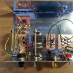
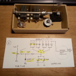
CCW from top left: Balanced Mixer/Product Detector, Local Oscillator/Buffer with VXO mounted vertically, tuning capacitor, Mic Amp, and Audio Amp with just the tinned pads on the board

All that’s left to have a working receiver is building the Audio Amplifier which I have already laid out, I just need to solder the parts down and test. After that I need to build the RF Amp to have a transmitter. I will want to also complete the Low Pass Filter before transmitting though. I don’t want to splatter the band or anything.

So the schedule for now looks like a completed Beach 40 transceiver should be on the bench next weekend or there abouts.

That’s all for today.

73,
~Jon KK6GXG

Marker Generator and more

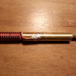
20150507_190019Picking up where I left off in the last post, I got the drill bits and finished the 40 meter Helically Wound Vertical antenna. I will get a project page up soon.

Now when I say “finished”, what I mean is the antenna is useable. I still need to seal and cover it but I wanted to get it all tuned up first. As far a receiving goes, the vertical is out performing the dipole strung in the house just sitting on the floor leaning up against the wall next the operating station, so it’s looking good.

I need to finish the tuning with a transmitter on it. Since the only transmitter I have for 40 meters is a CW 250mW transmitter I am holding off on that.

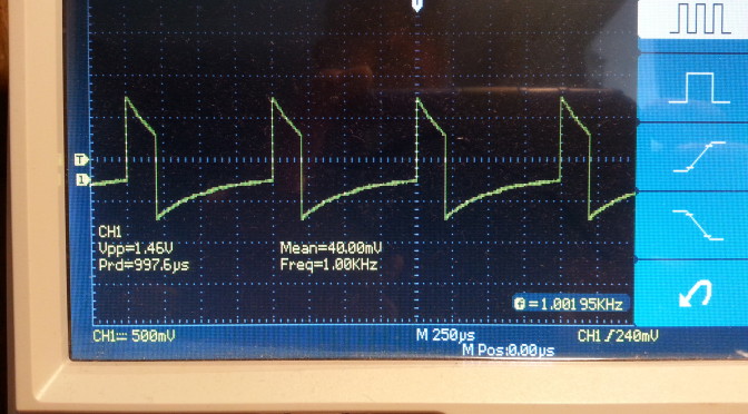
20150508_121409In the mean time I put together a Marker Signal Generator. The design takes an 8 MHz crystal and divides the signal down several time ending up with the desired 1 kHz signal with many harmonics to mark out a tuning dial in 1 kHz increments.

20150508_150243It was fun to build and I leaned a little about some ICs I had never used and some of the basics of working with multiple devices in a single package.

When I came to function, I was very disappointed. The oscillator was anything but stable and we very dependant on an extremely stable input voltage. The onboard diode voltage regulations stunk so I tuned down the power supply from 12 volts to the 5 the ICs need.

20150508_153648At this point I was finally able to calm down the oscillator and get close to 1 kHz I was hoping for. A millivolt up or down and the frequency was out. Not a particularly useable device as it sits but it does give me some ideas for using out of band crystals to generate a signal.

As always, this is the whole point, to experiment and learn about RF design by doing, not just reading and modeling on a computer.

The big news, and the reason I missed a post last week is that I have been doing some research on finding my next big build project. The winning design was the Beach 40 by VK3YE. I have been scouring the web looking for a simple phone (voice) transmitter. I was hoping for SSB (Single SideBand) but the Beach 40 DSB (Double SideBand Suppressed Carrier) is simple and straightforward as is.

IMG_20150513_125237Being me, I had to make some modifications to the design and tweak a few things. One of the great things about this design s that it uses discrete components rather than ICs.

At one point Peter (VK3YE) recommends changing the audio amplifier to one that uses the LM386 chip rather than discrete components because the output is rather low. Since one of the main reasons I chose this project was to keep to available discrete components I went out in search of a different audio amp.

Enter Arv Evans K7HKL and his Discrete Component AF Amplifier paper. By the way, at least via email, Arv is a really nice guy. Thanks for the help Arv!

20150513_170104Now with the circuits mostly settled and parts enroute, Digi-Key arrived a day early! 🙂 I sat down tonight and began kitting the parts for each of the transceiver subsections beginning with the Super VXO. I am only installing one crystal set right now but the plan is to set it up for several banks of crystals. I also had some ideas as to using the banks for multiple bands as well as sections of a single band, but that’s for later.

20150513_202942I also kitted the Local Oscillator/Buffer and the Balanced Modulator/Product Detector sections. There are a few bits that will need some refinement, mostly inductors, but these will be addressed as needed.

And speaking of inductors, since I sent back that crappy one I am still in need of one. I will be ordering one tomorrow because I wont get far in this build without one. The goal is to have this radio up and running before Field Day June 27-28.

Look for a project page soon.

Till next time, 73,
~Jon KK6GXG

New-To-Me Signal Generator

120 kc (kHz) to 200 mc (MHz)

On Saturday I picked up a few things at the De Anza Electronics Flea Market. The most impressive acquisition would be the Lafayette Signal Generator for $20.

I have been needing one and I was dreading the prospect of having to build one and having a tough time without the right tools for calibrating it, so this was a great find and a steal of a value, though I didn’t know it for sure until today.

One thing I have learned about buying used electrical/electronic equipment, particularly in at a flea market, is that you have to take your time and open it up, get documentation, inspect and clean the equipment before attempting to use it, or plug it in for that matter.

20150414_075130 Sunday was opening day. I noticed right away that I would need to replace the power cord grommet as it was in two pieces. I didn’t actually get to anything else until today.

Today I inspected all of the wiring and components, looked for hot spots and anything that would indicate an over heat. Having found nothing of the sort I moved on to cleaning, which there was surprisingly little to do. I made sure the tubes were cleaned and had no fingerprints on them. Now that I have a piece of tube equipment I will need to get a tube tester. 😉

With the cleaning done it was time for the plug-in and smoke tests. No pops and and no smoke! I let everything warm up and burn in for a good twenty minutes before starting any tests.

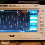
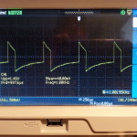
Testing with the oscilloscope began with the AF (audio frequency) side of the generator. After the twenty minute warm up period the “approximately 400 cycles” audio tone as specified in the manual turned out to be stable at 388 cycles (Hertz). I can work with that.

“kc” is kilocycles. The term is essentially the same as the more familiar kilohertz along with “mc” megacycles being the same as megahertz. The change over in terminology occurred slowly from the mid 70s to the mid 80s. Many hams still use kc and mc. I use them interchangeably depending what I am referencing or who I’m talking with. This piece of equipment has frequency labeled on the dial as kc and mc.

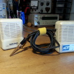
20150417_152319Moving on… The generator did its first diagnostics job with a portable amplifier I have had for a very long time (the one on the right). I clipped on the amp to the audio out and it turn out the volume control on the amp is trashed from banging around in my tool bags for a couple of decades so I will need to replace the potentiometer in that this weekend.

I then moved over to the RF (radio frequency) side of the generator and clipped on the oscilloscope. The RF side is divided into 5 switchable bands. I checked each band by referencing the frequency on the dial with the frequency on the O-scope. All five bands checked out very closely to the dial. A little lead or lag here-and-there, but overall pretty close for this equipment and its age which I’m guessing is about as old as me (made in the mid/late 60s).

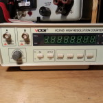
20150417_152206The frequency counter I purchased last year has been giving me problems. New equipment, cheap (figuratively and cost), and no manual. With the help of the new sig gen and the oscilloscope I managed to fix a couple of minor problems and figure out the modes on the counter in the process. Looks like the electronics bench is finally coming together.

Now that I can check the receivers I build I can also check the transmitters I plan on building. I can also check portions of the radios as the construction moves forward. I plan on building more of my own test equipment but it’s nice to have a reference point or two to calibrate off of.

I also did some diagnostics on the 40 meter direct conversion receiver project and updated the project page… some very interesting results, you should take a look. 🙂

A productive day I think.

73,
~Jon KK6GXG