
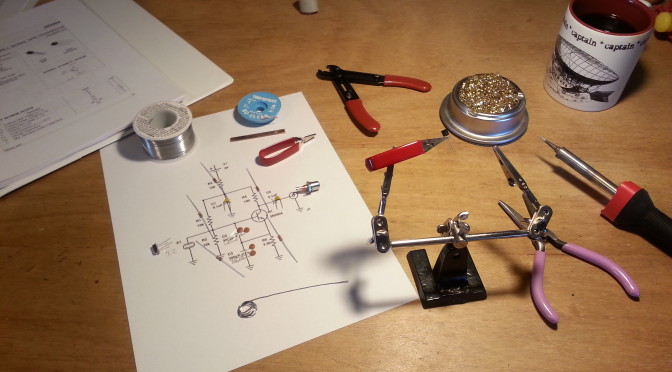
As I was wrapping up the build on my Direct Conversion Receiver 1 I discovered I needed a signal generator to start the testing. At first I just need something stable to inject a specific frequency and ball-park that the receiver is actually in the right frequency neighborhood.
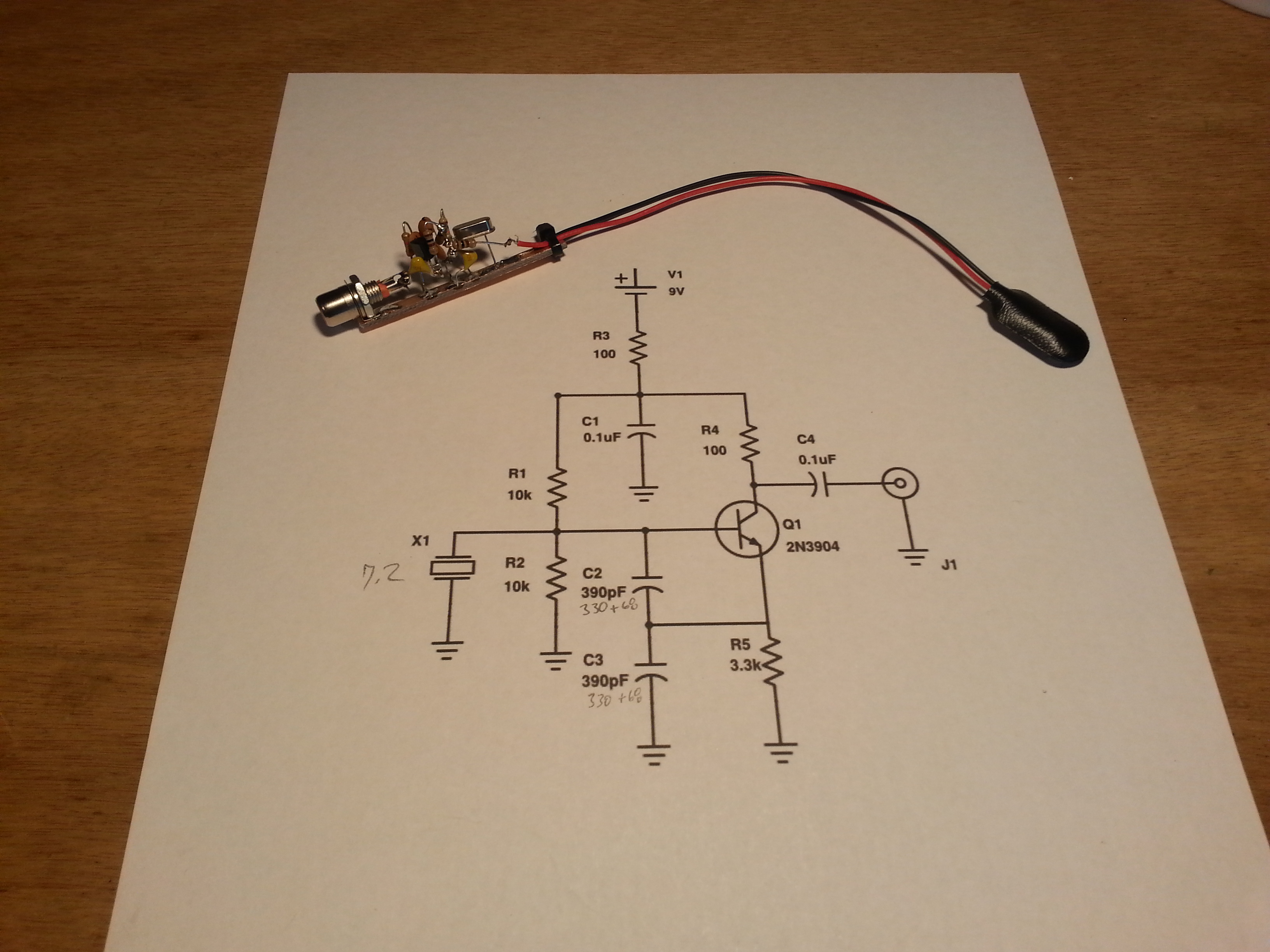
 This design is from EMRFD chapter one also (can you tell I am working my way through the book?) I also happened to have all the parts, well sort of. The C2, C3 capacitors called for are 390pF. The closest I could get was series 330pF and 68pF to make 398pF each.
I picked up a bag of 7.2 MHz crystals for stock last month so this worked out well. The resulting frequency of the oscillator is 7.25 MHz and is very stable. A thought crossed my mind, a twin variable cap tied to C2 and C3 should pull or push the crystal frequency a little and the addition of a multi position switch and a stack of crystals should offer a multi band function.
This particular circuit as-is works great and as a single frequency signal generator/injector for bench testing. Or as an very low power beacon transmitter.
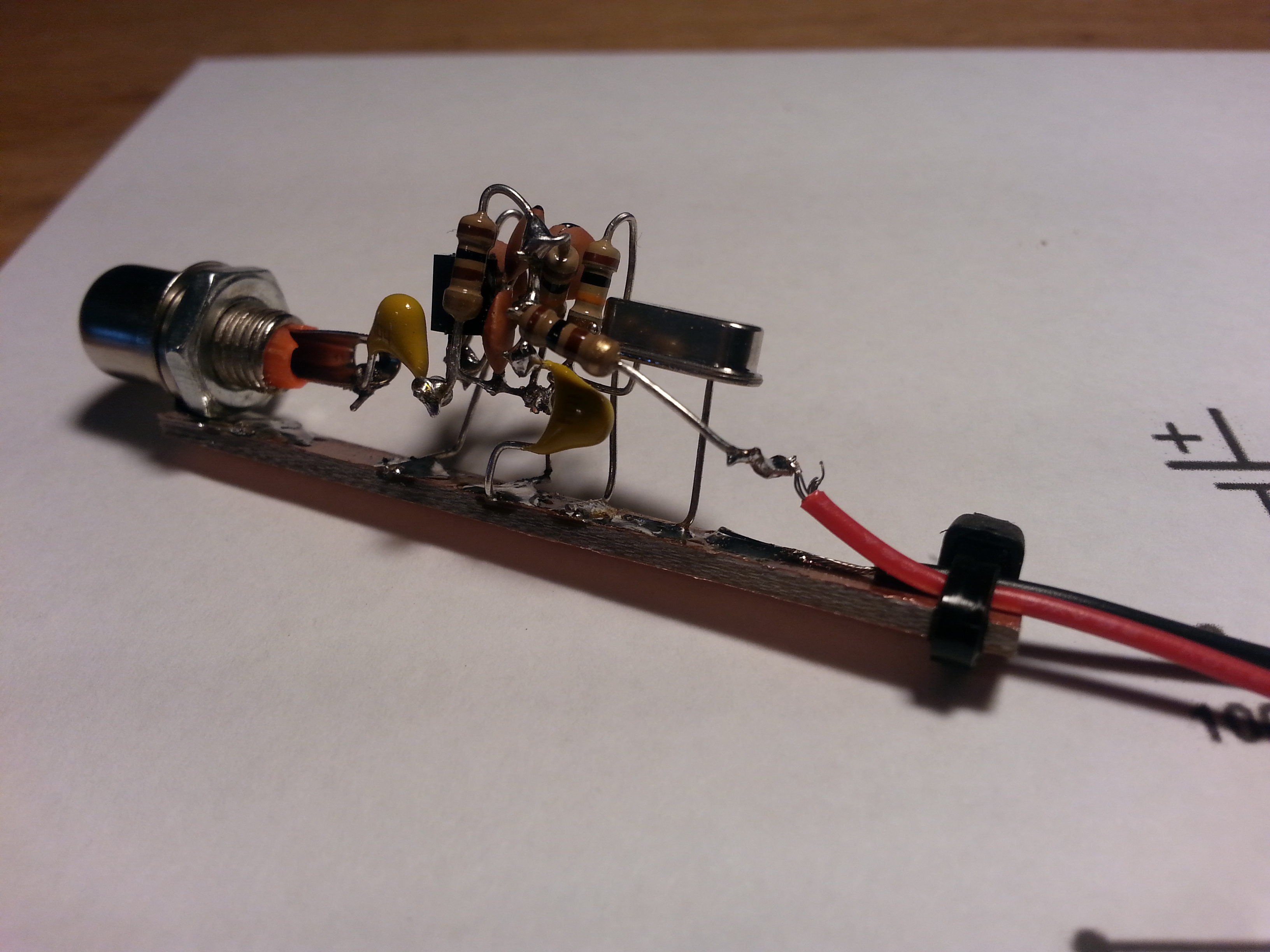 Building this project I chose to go full on ugly. The entire circuit was built off the transistor and each component added on top of each other. I didn’t take any pictures of the cluster of parts before mounting it on the sliver of PCB, sorry.
Click on the picture of the assembled circuit and you can see the cluster. Just imagine all of the components tied to ground were pointing down, the R3 resistor tied to positive power was sticking out horizontally as was the C4 capacitor connecting to the J1 RCA jack in the opposite direction.
 After the cluster was assembled, I soldered all of the ground connections to the sliver of PCB. With all of that done I soldered the ground tab of the RCA jack to the board then the C4 capacitor leg to the core of the jack. The last connections were the power connections and zip-tying the leads to the board.
There are just a few more pictures that I uploaded to Flickr.
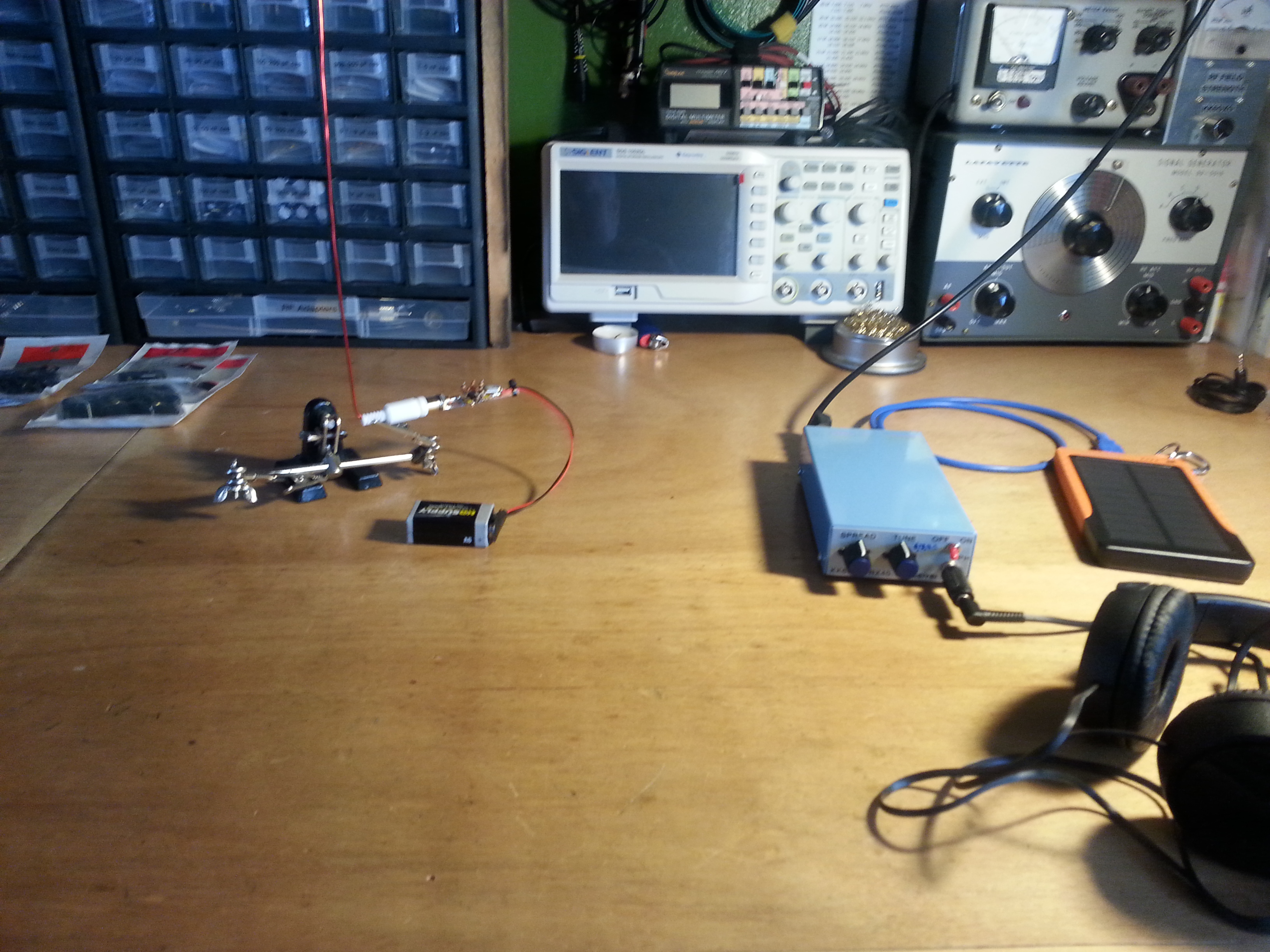
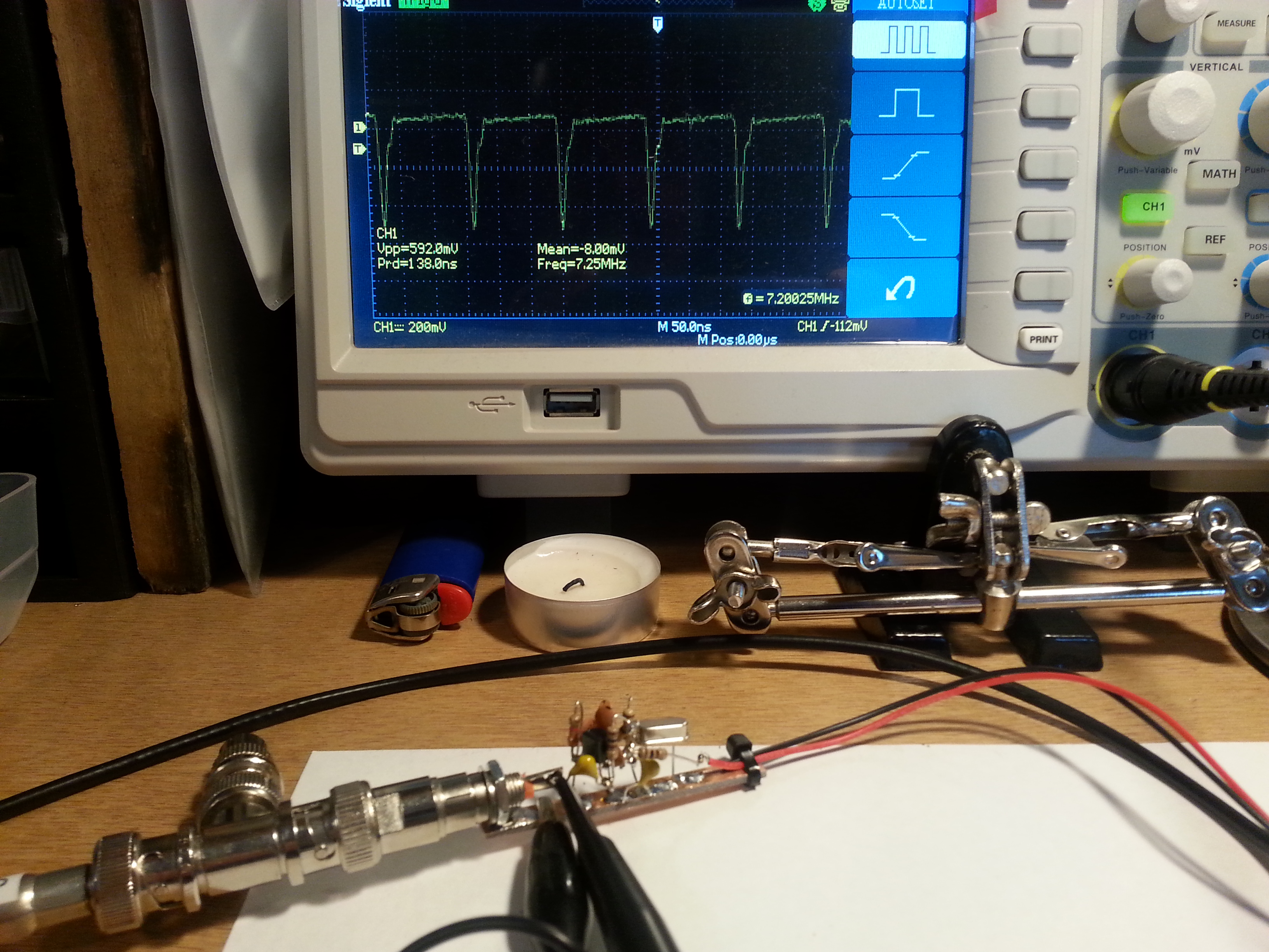 After the build I hooked up the signal generator to a BNC T-Junction and a 50Ω dummy load and connected it to the oscilloscope to check the frequency. A nice consistent waveform and rock solid 8 mV current draw and 2.25 MHz frequency.
An easy project that has some potential to make a serious multi-band signal generator for bench testing, also a good jump off point to a series of VXO projects.
2014-04-19
I tried, to no avail, to pick up a signal with the Direct Conversion receiver project. Turned out that the receiver was well below the 40 meter band running 6.4 MHz to 6.8 MHz. Needless to say it wasn’t going to pick up a signal from this transmitter.
 After tuning the receiver up to the 40 meter amateur band, actually it covers the band and almost 100 kHz beyond in both direction, it now picks up this transmitter very well with a 10 inch wire antenna on the transmitter just sitting on the desk near the receiver. No connection required.

I am very happy with both projects and the new addition to the bench tools that made it all possible, the Lafayette signal generator.
There are several things that may evolve from this little transmitter. If I take this basic project and extend it into something else I will post link(s).