Busy weekend for me.
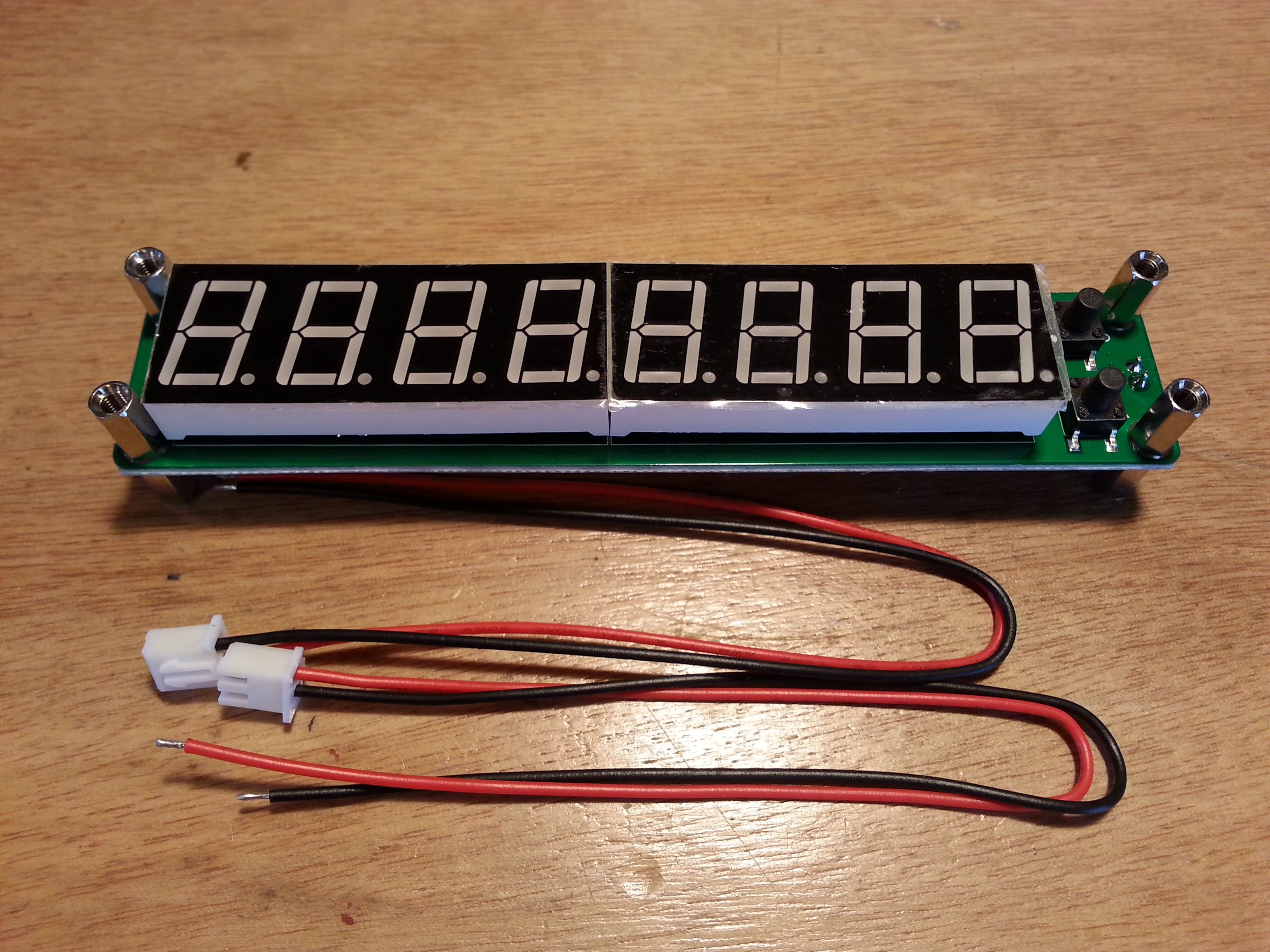 Before moving on to Beach 40 progress, I got something else in the mail. A frequency counter module I ordered off eBay for ten bucks. I am thinking about using it in a future radio project as a digital frequency display. Not sure what project, but it beckoned to me and I figured it might work out well.
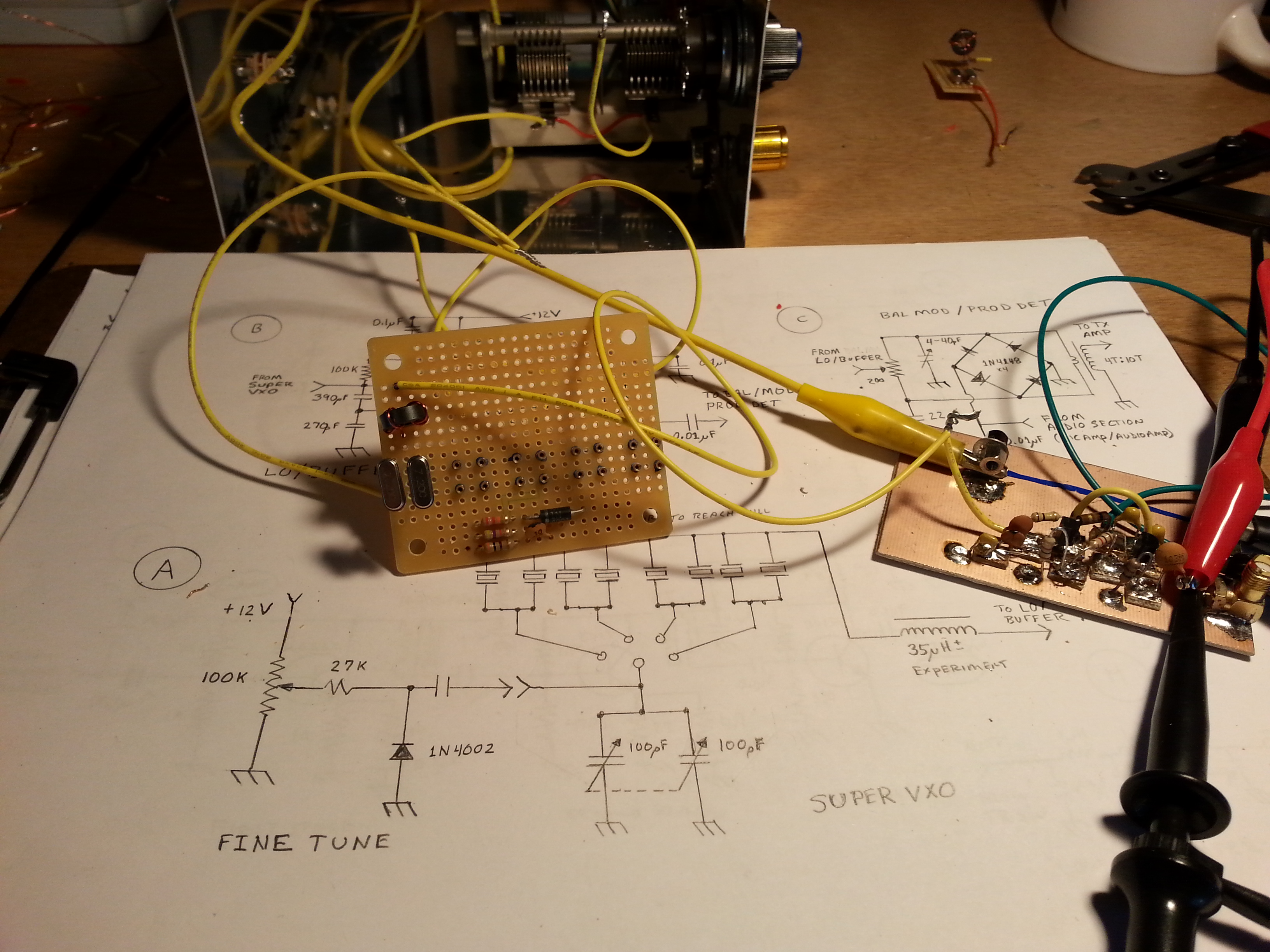
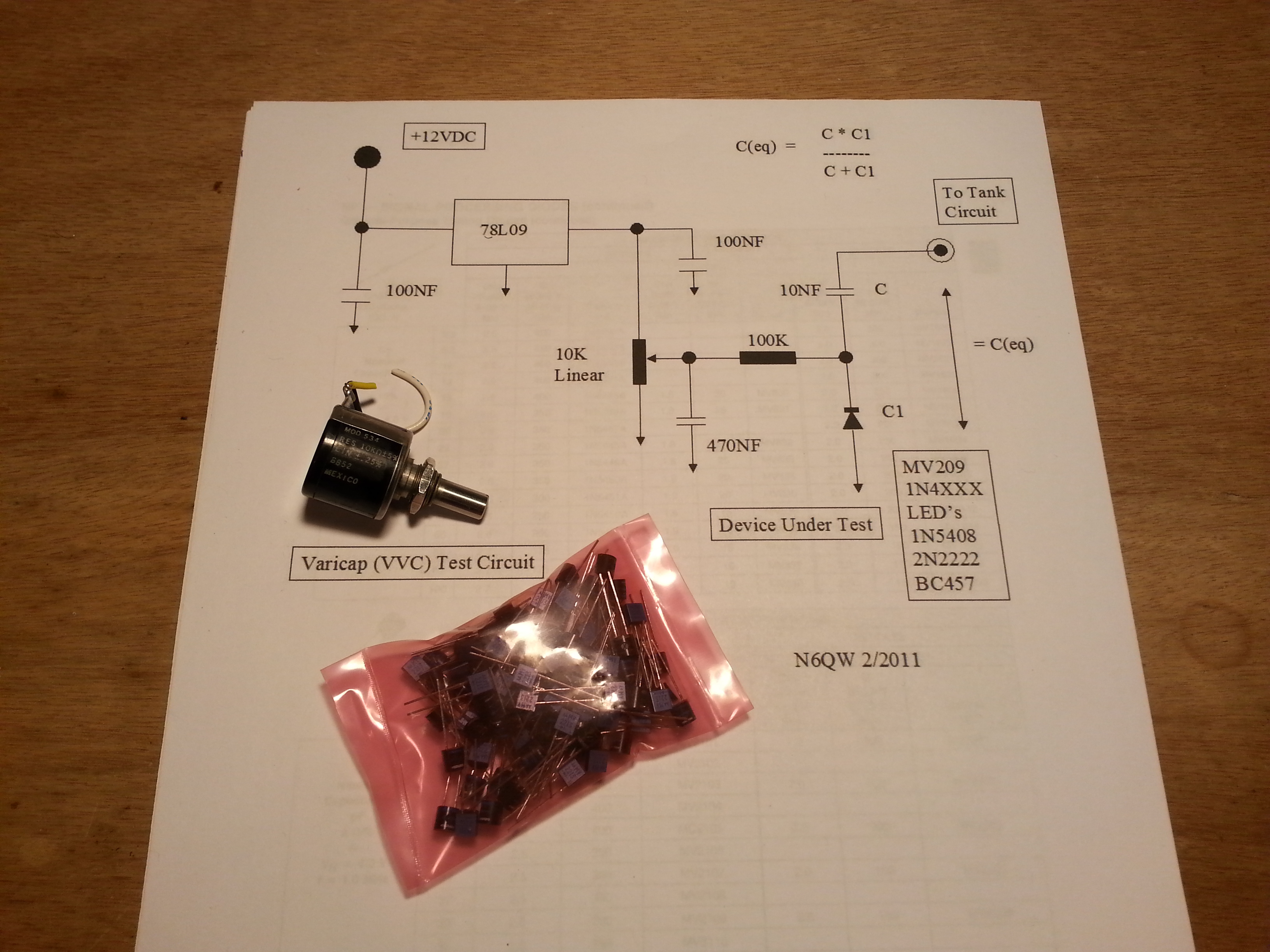 In a related sidebar, I have been doing some VFO research. I have been looking at several options and one that seems simple and efficient is using varactor diodes to replace the air dielectric capacitors in tuning circuits. I have some ten-turn potentiometers and found a good deal on Motorola 68ρF varactors so I bought a bag of 100.
I found N6QW’s website with some great information including a test circuit for testing the tuning abilities of various diodes and transistors. Definitely more to come on this venture after the DSB project is done.
Now, on with our regularly scheduled program…
 In the last post I talked about skipping the Balanced Modulator/Product Detector and moving on to the Audio Amplifier.
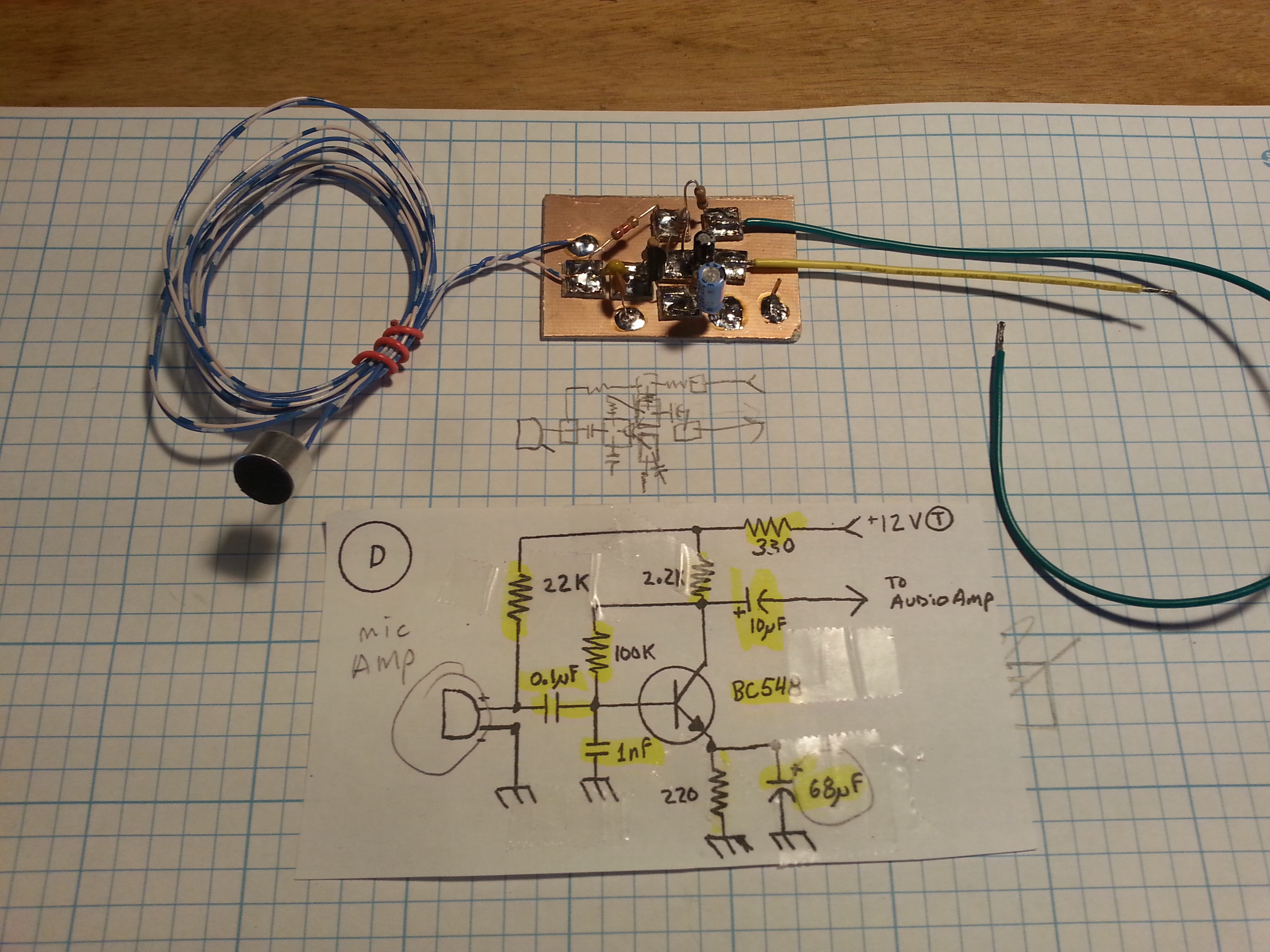
I built the Audio Amp and got everything all tied in to the panel mount components.
 I still haven’t tested the Audio Amp yet and I am saving that for after I get all of the sections built out.
About the time I finished up the Audio Amp the 200Ω potentiometer I was waiting on showed up. With the parts in hand, I moved on to the BM/PD.
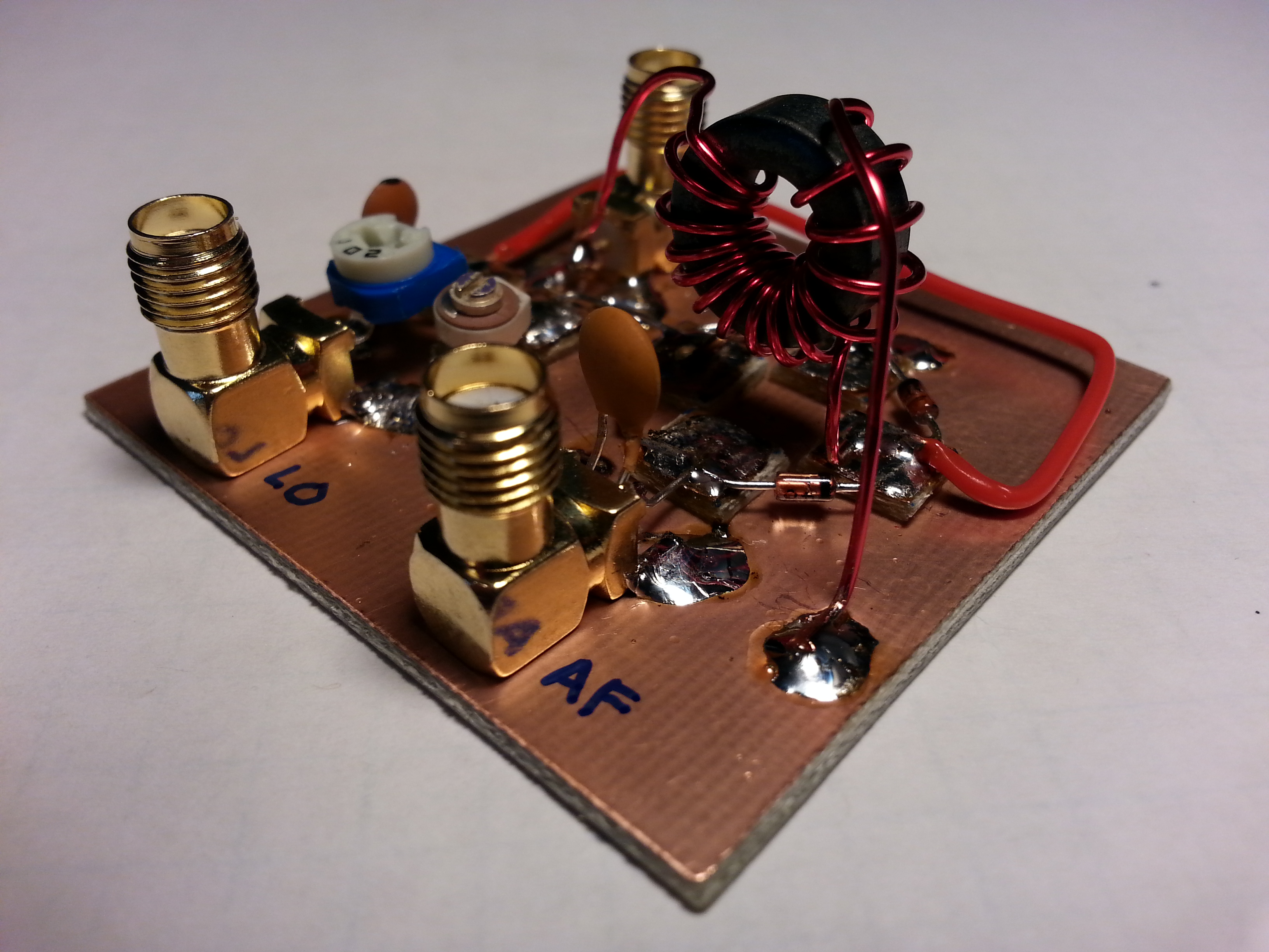
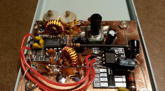
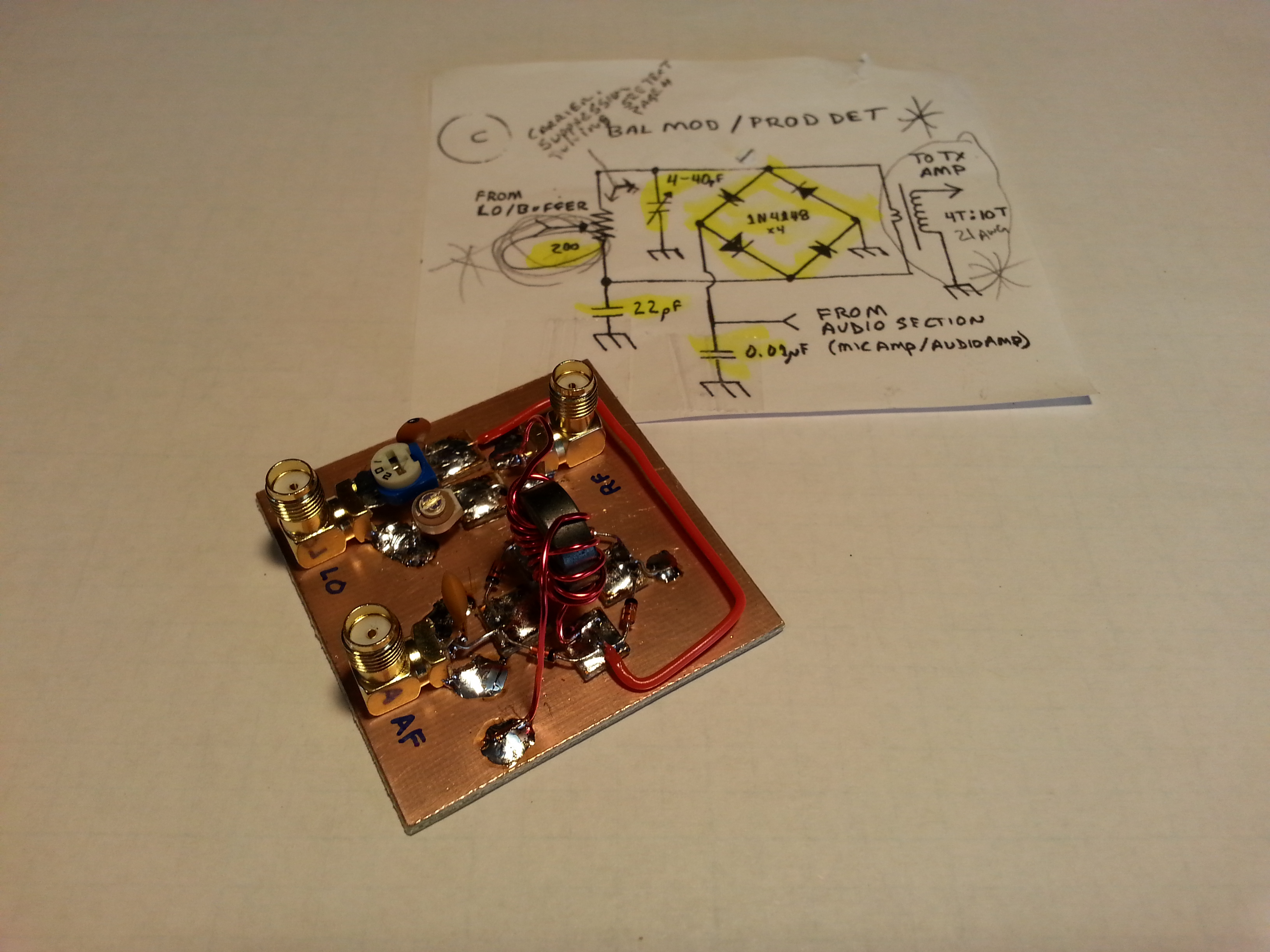 The BM/PD build went well. with no real surprises. The diode ring ended up being laid out in an actual ring configuration with the RF transformer being mounted right in the middle.
The one thing I don’t like about this layout is the really long lead from one side of the diode ring all the way around to the other side of the board to the potentiometer. I don’t know if I can come up with a better layout in a future rendition but for now it should be fine.
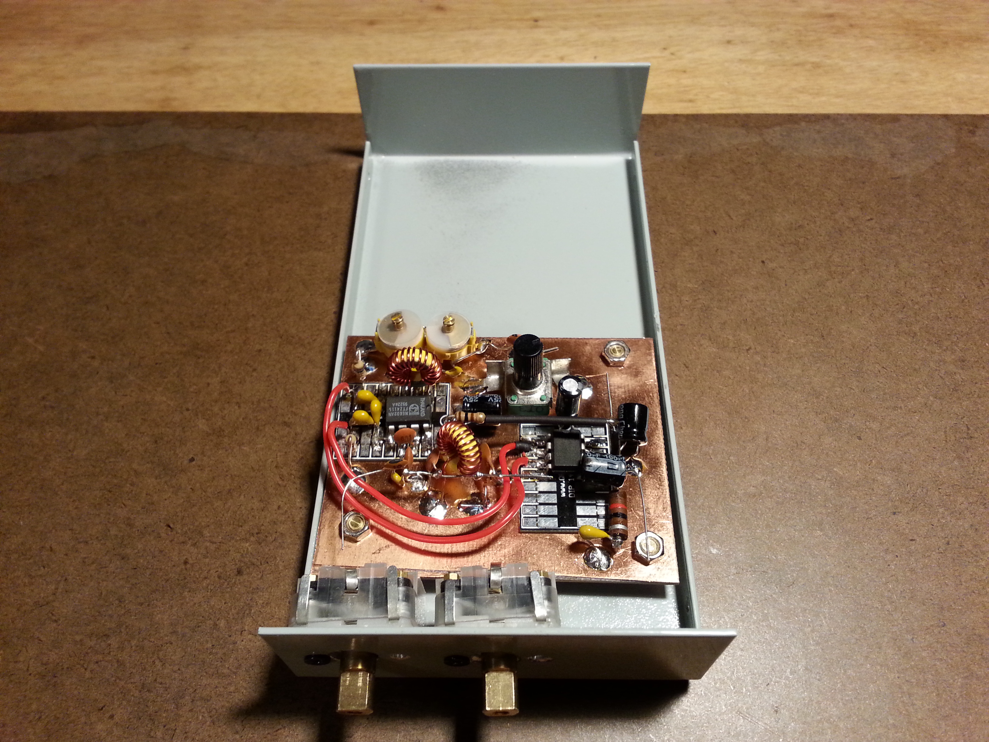
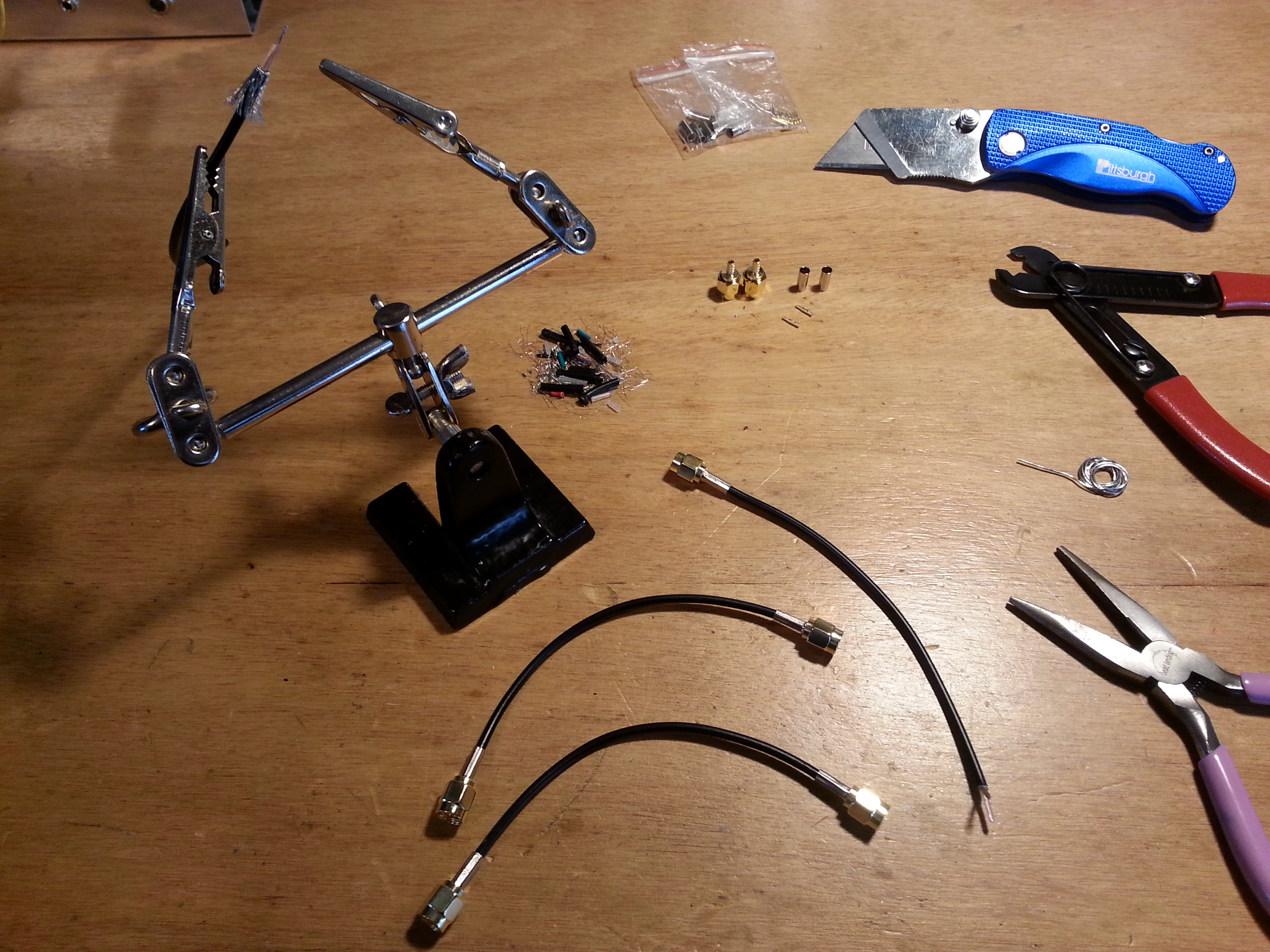
 One of the first things I started with today was building the interconnect cables out of RG174 coaxial cable and SMA connectors. I considered MMX connectors since they just push on rather than thread on but they are way expensive. I have seen a number of builders use coax interconnects for modularized construction and it makes separation for experimentation much easier.
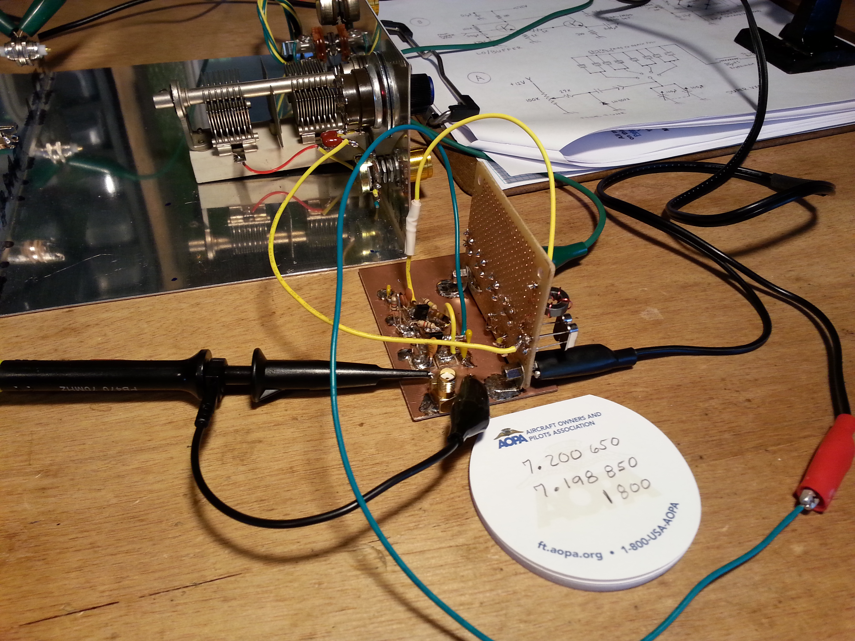
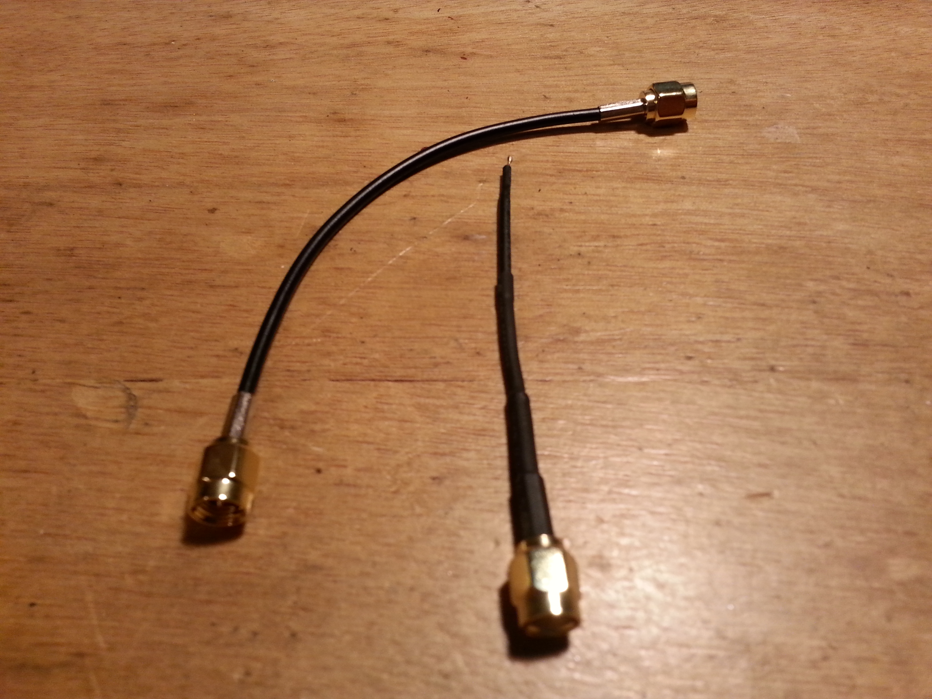 One cable I made was actually an antenna, a test antenna at least. For testing transmission sections giving them something to radiate out of. By using a receiver near the transmitting device I should be able to copy the transmission. It’s the one on the right if you hadn’t guessed.
 Cables, of any kind, are one of those things that can seem fairly easy to do, but when they go bad, they can go epicly bad and it can be hard to detect. The only preventative effort I know of is to take your time, use a light touch, don’t force things, and pay attention to detail.
I made 4 interconnects, 1 antenna, and one single end cable for connecting to the antenna outlet. It took a coupe of hours, but all of them are solid mechanically, and test to be solid electrically.
 After getting the cables done, I hooked up the antenna and one of the interconnects but I still haven’t done any of testing beyond the Local Oscillator.
I have a lot of testing to do but I’m almost done with the modules so I wanted to plug away and finish up the modules.
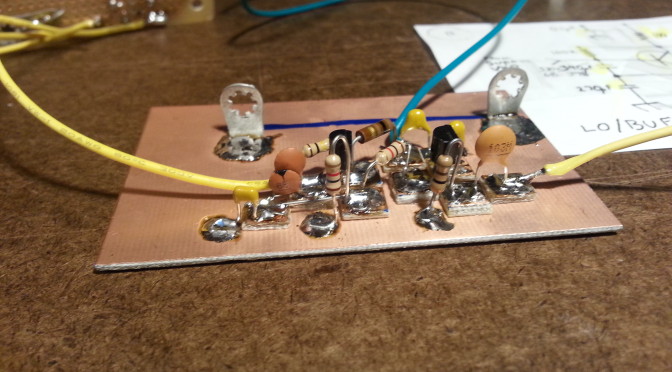
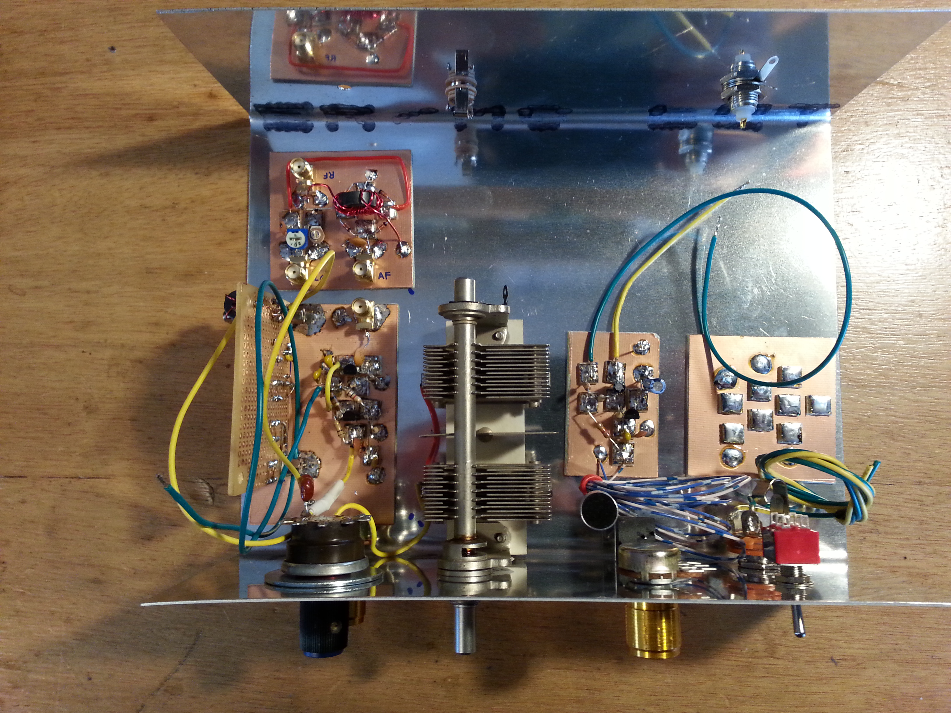
 The last thing I worked on before turning off the soldering iron was the three stage RF Amplifier.
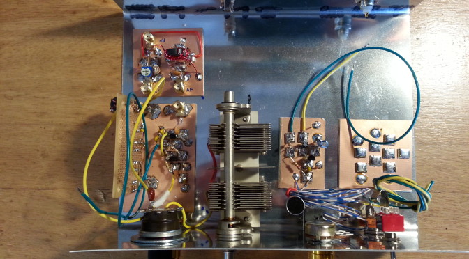
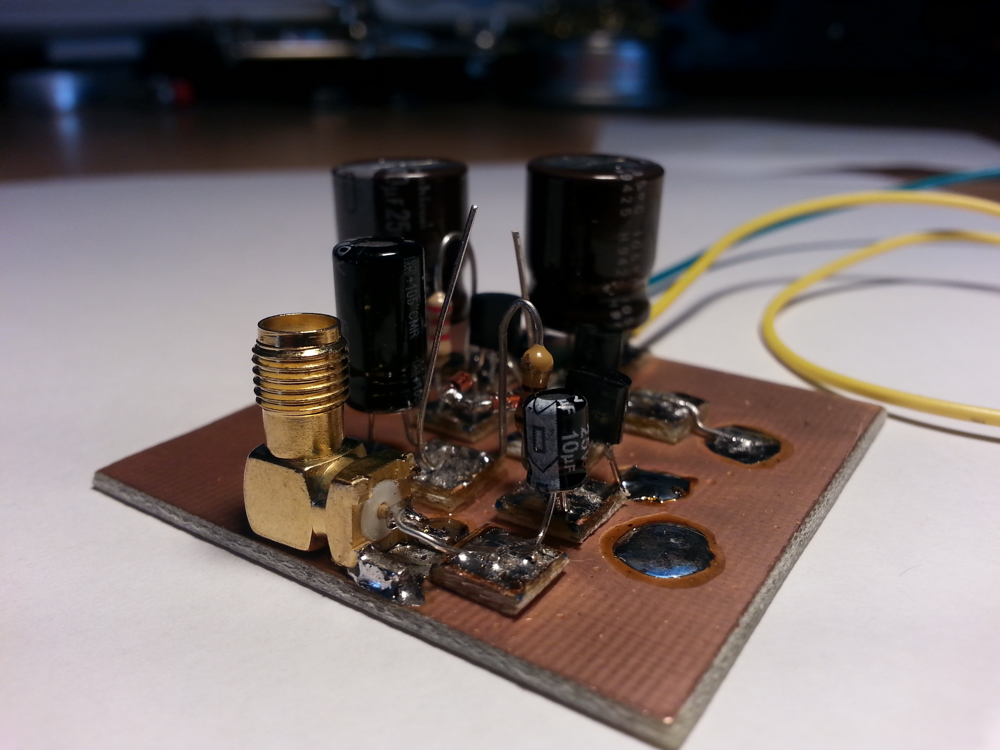
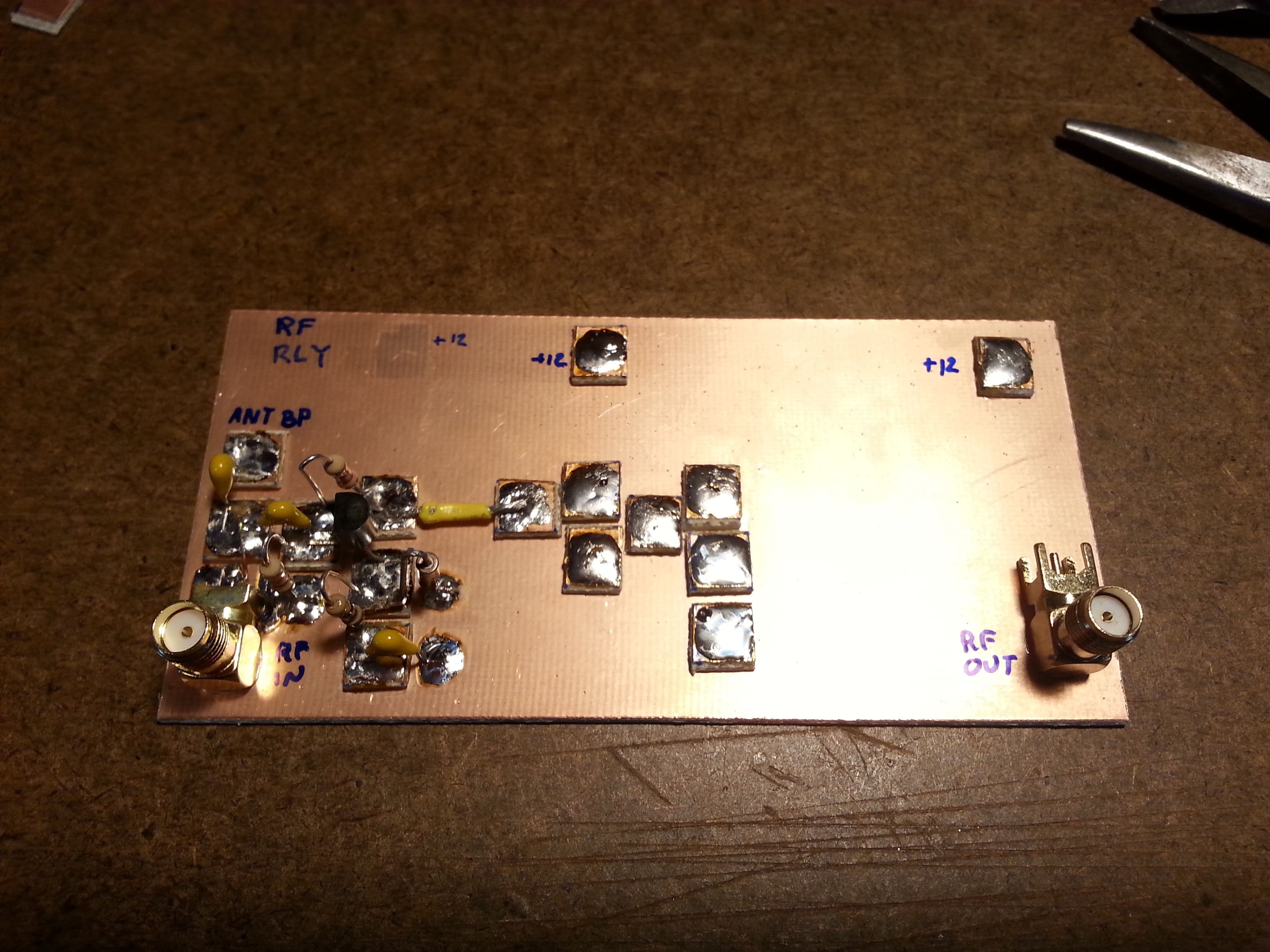
The pic is the first stage, a buffer stage. I started the board with a configuration in mind but by the time I got to the third stage I had shifted a few things around.
 One thing I wanted to point out is the spacing of the stages. In this pic I have most of the second stage done and the pads for the third stage laid down. The gaps between stages are for the addition, if needed, of shielding between the stages. This amp is fairly low power so I don’t think it will need the shielding, But I wanted to make the option available.
 The third stage saw several pads moved and things reconfigured a little. The yellow leads are the RX Amp Bypass (short lead) and Amplified RF (long lead) lines going to the relay circuit which after a lot of thought this evening will be replaced with cable ports and the relay section will be moved off this board entirely onto it’s own module.
The other bit on the RF Amp board that still needs work are the two bifilar toroids that still need to be wound and installed. It sounds like a lot of work still to be done, but it is getting very close to First Contact.
Thats all for this post. May the magic smoke remain contained in all your circuits.
73,
~Jon KK6GXG