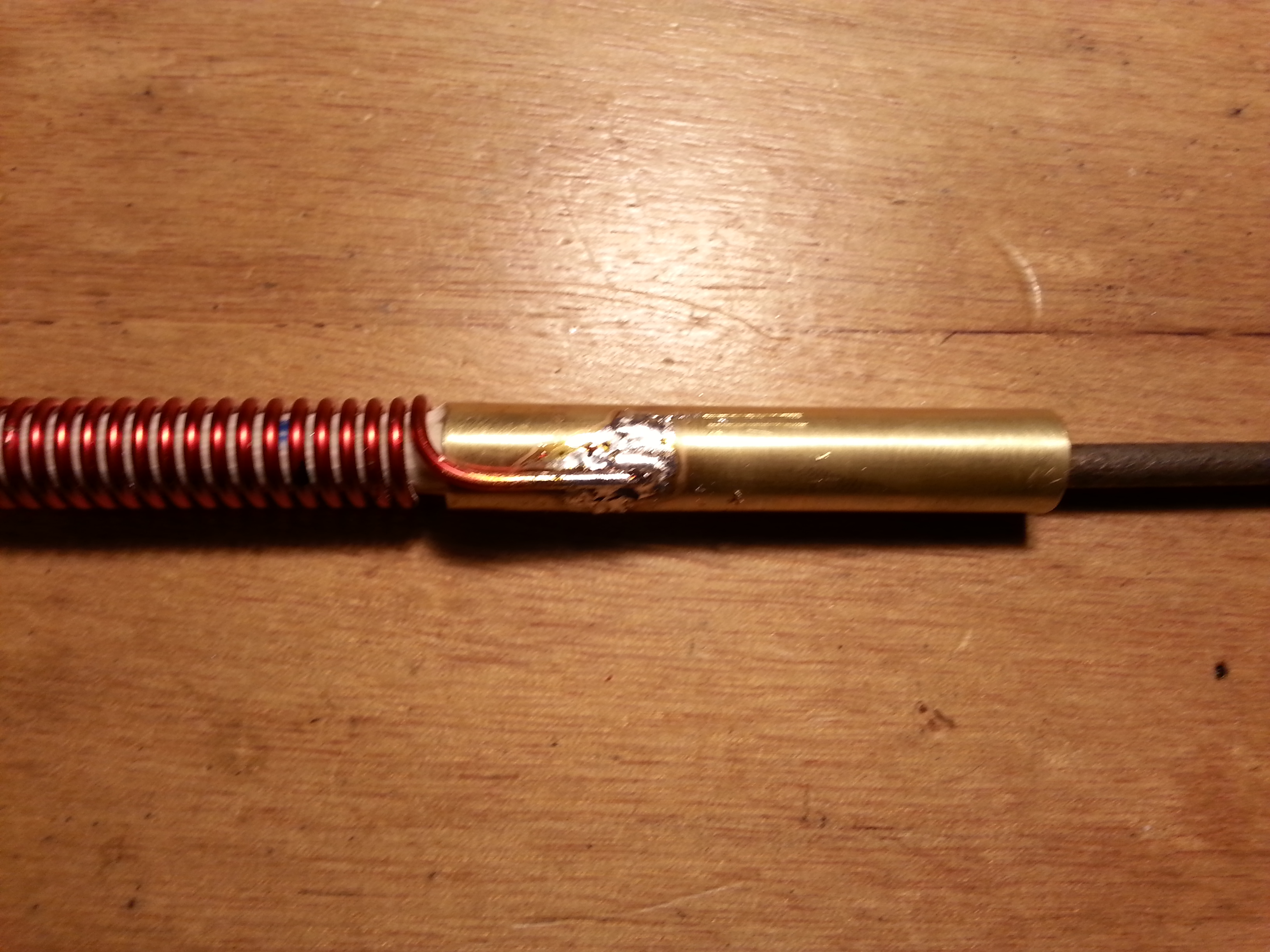
 Picking up where I left off in the last post, I got the drill bits and finished the 40 meter Helically Wound Vertical antenna. I will get a project page up soon.
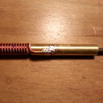
Now when I say “finished”, what I mean is the antenna is useable. I still need to seal and cover it but I wanted to get it all tuned up first. As far a receiving goes, the vertical is out performing the dipole strung in the house just sitting on the floor leaning up against the wall next the operating station, so it’s looking good.
I need to finish the tuning with a transmitter on it. Since the only transmitter I have for 40 meters is a CW 250mW transmitter I am holding off on that.
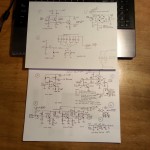
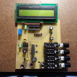
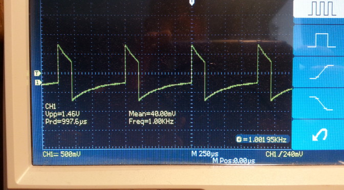
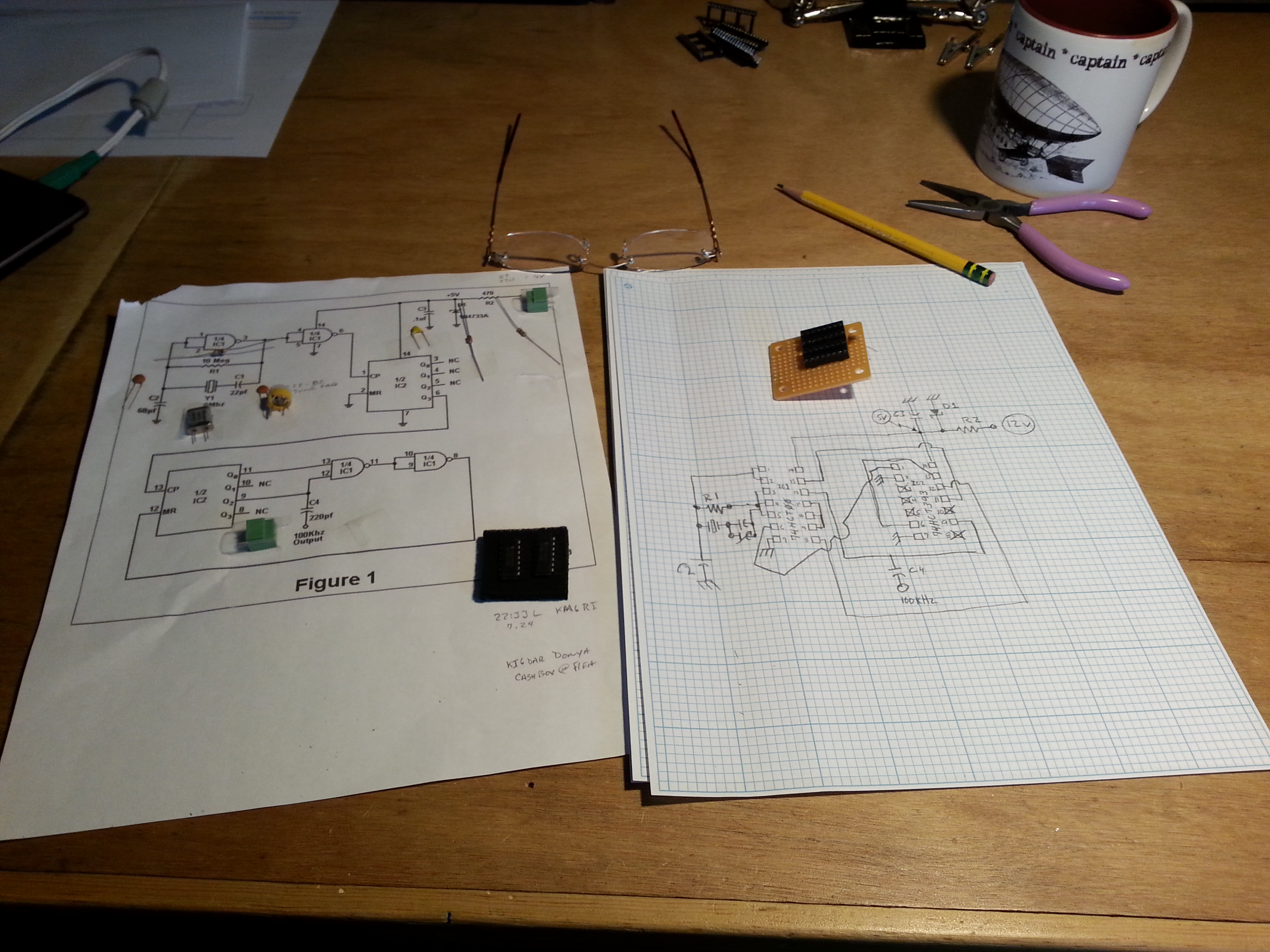
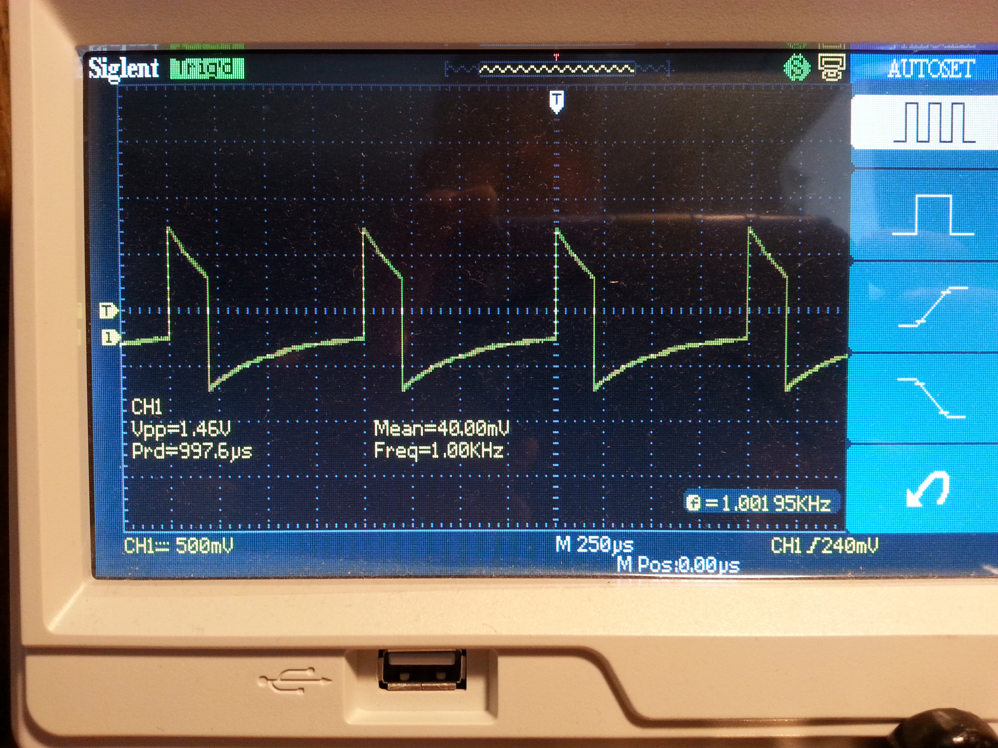
 In the mean time I put together a Marker Signal Generator. The design takes an 8 MHz crystal and divides the signal down several time ending up with the desired 1 kHz signal with many harmonics to mark out a tuning dial in 1 kHz increments.
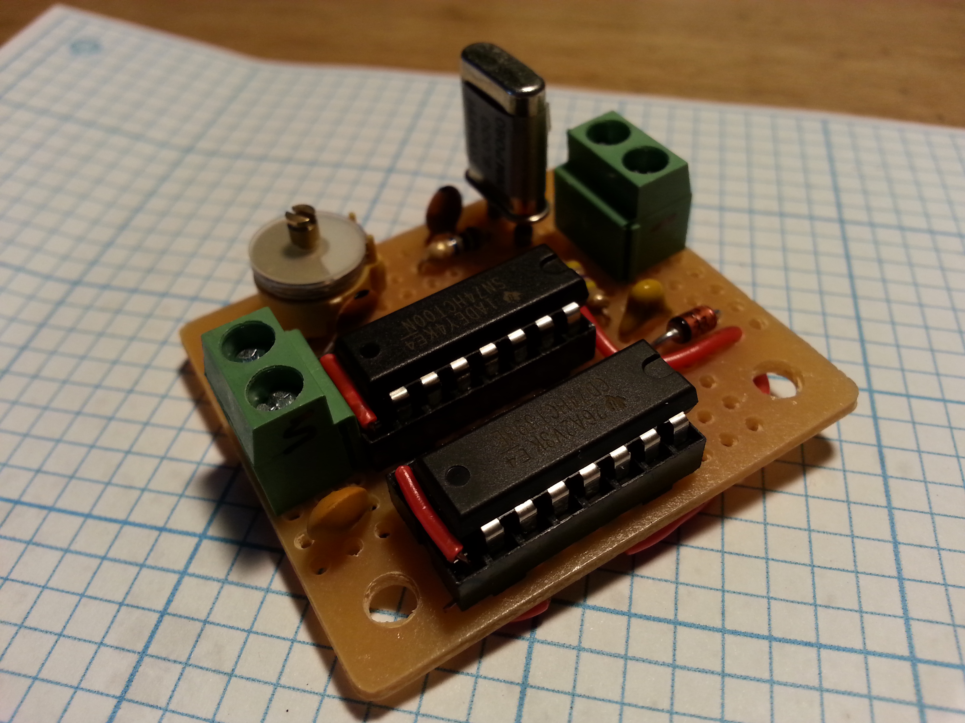
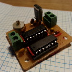 It was fun to build and I leaned a little about some ICs I had never used and some of the basics of working with multiple devices in a single package.
When I came to function, I was very disappointed. The oscillator was anything but stable and we very dependant on an extremely stable input voltage. The onboard diode voltage regulations stunk so I tuned down the power supply from 12 volts to the 5 the ICs need.
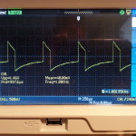 At this point I was finally able to calm down the oscillator and get close to 1 kHz I was hoping for. A millivolt up or down and the frequency was out. Not a particularly useable device as it sits but it does give me some ideas for using out of band crystals to generate a signal.
As always, this is the whole point, to experiment and learn about RF design by doing, not just reading and modeling on a computer.
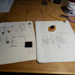
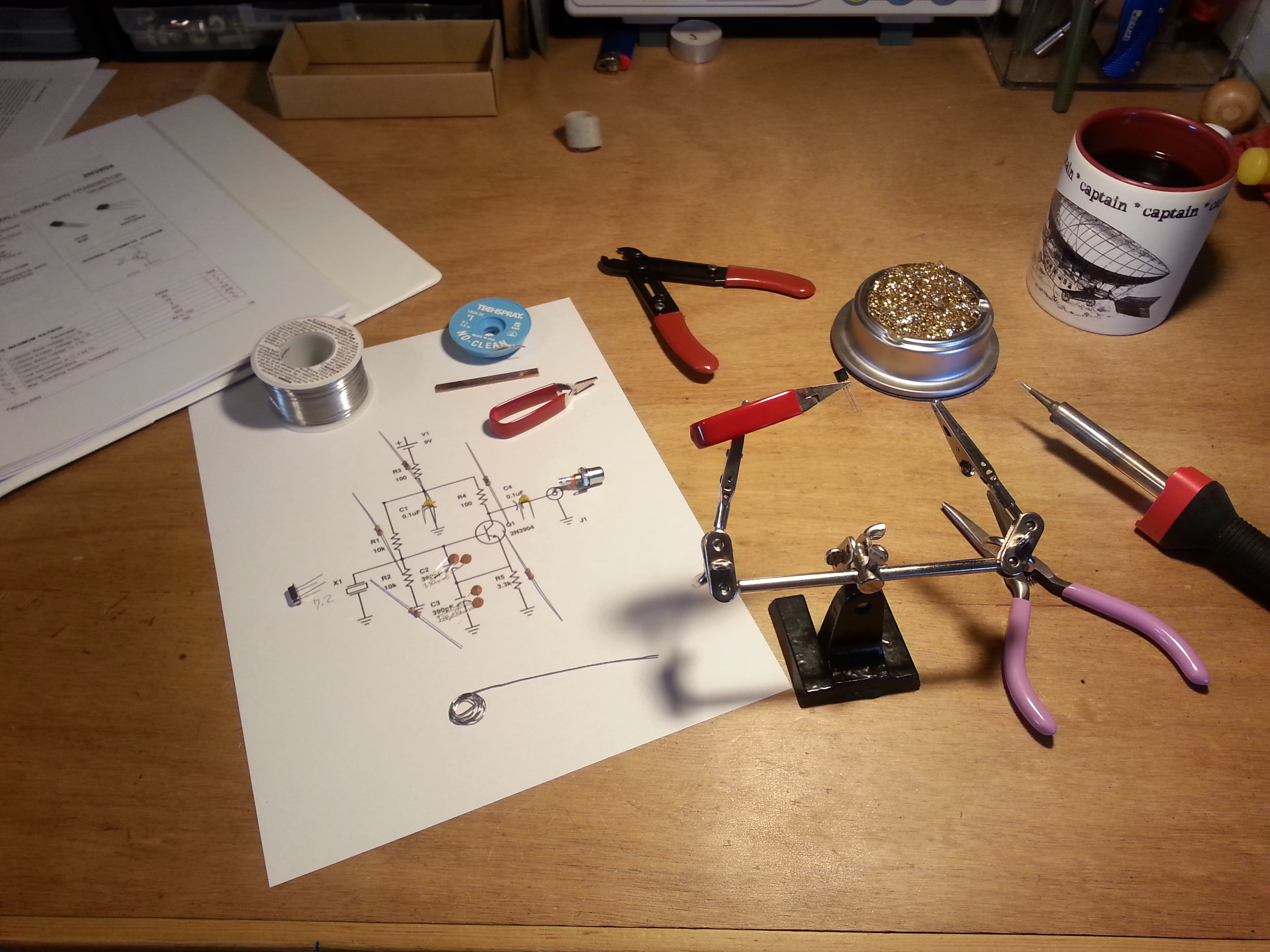
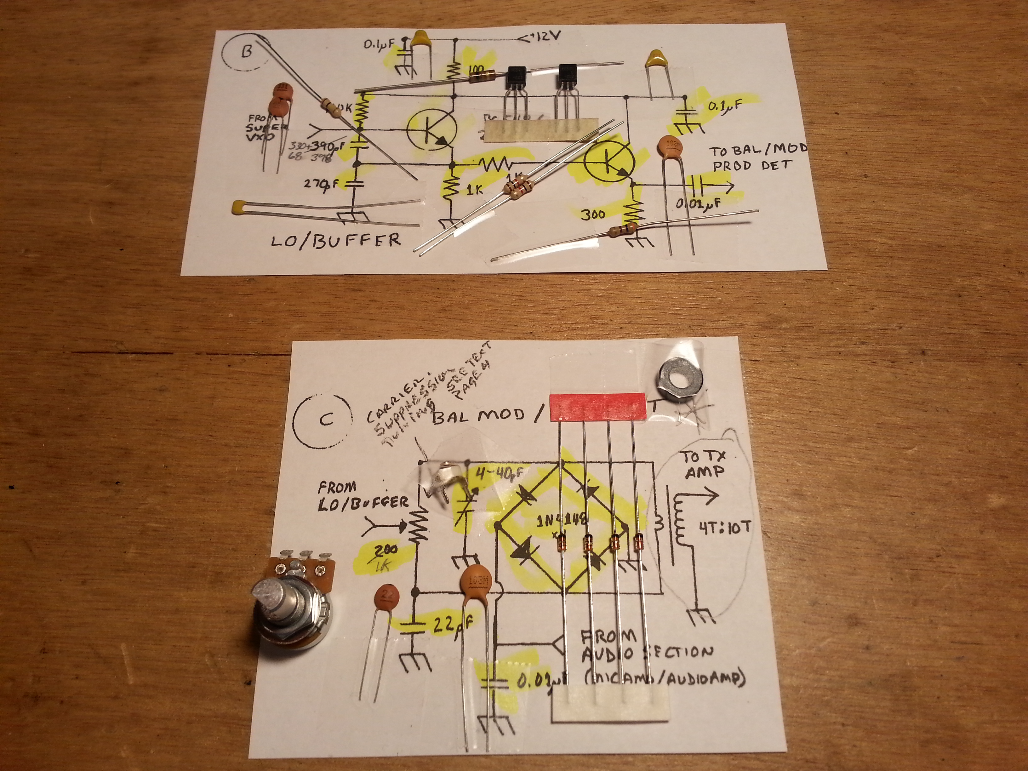
The big news, and the reason I missed a post last week is that I have been doing some research on finding my next big build project. The winning design was the Beach 40 by VK3YE. I have been scouring the web looking for a simple phone (voice) transmitter. I was hoping for SSB (Single SideBand) but the Beach 40 DSB (Double SideBand Suppressed Carrier) is simple and straightforward as is.
 Being me, I had to make some modifications to the design and tweak a few things. One of the great things about this design s that it uses discrete components rather than ICs.
At one point Peter (VK3YE) recommends changing the audio amplifier to one that uses the LM386 chip rather than discrete components because the output is rather low. Since one of the main reasons I chose this project was to keep to available discrete components I went out in search of a different audio amp.
Enter Arv Evans K7HKL and his Discrete Component AF Amplifier paper. By the way, at least via email, Arv is a really nice guy. Thanks for the help Arv!
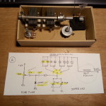 Now with the circuits mostly settled and parts enroute, Digi-Key arrived a day early! 🙂 I sat down tonight and began kitting the parts for each of the transceiver subsections beginning with the Super VXO. I am only installing one crystal set right now but the plan is to set it up for several banks of crystals. I also had some ideas as to using the banks for multiple bands as well as sections of a single band, but that’s for later.
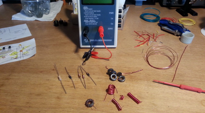
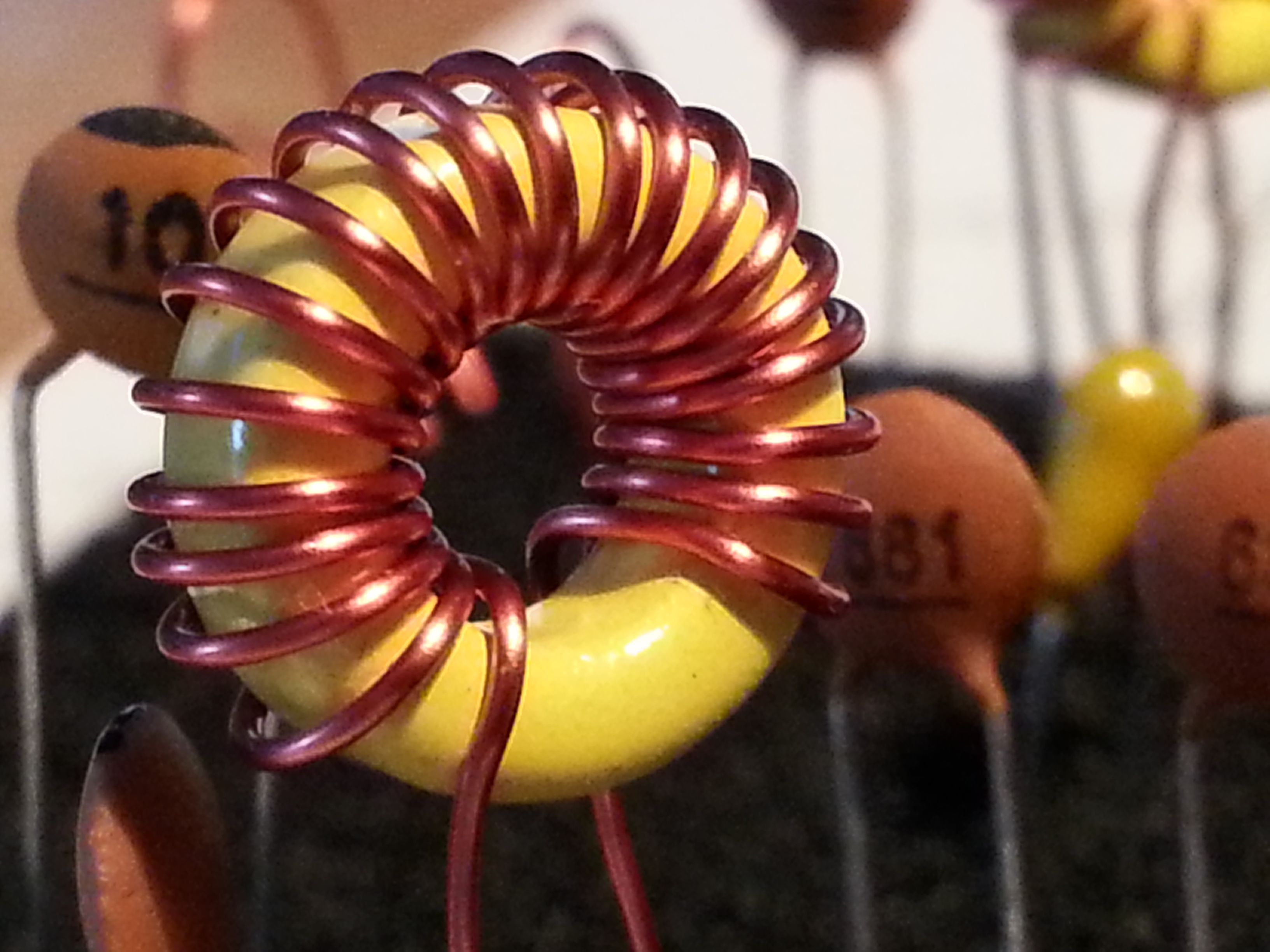
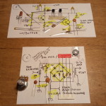 I also kitted the Local Oscillator/Buffer and the Balanced Modulator/Product Detector sections. There are a few bits that will need some refinement, mostly inductors, but these will be addressed as needed.
And speaking of inductors, since I sent back that crappy one I am still in need of one. I will be ordering one tomorrow because I wont get far in this build without one. The goal is to have this radio up and running before Field Day June 27-28.
Look for a project page soon.
Till next time, 73,
~Jon KK6GXG

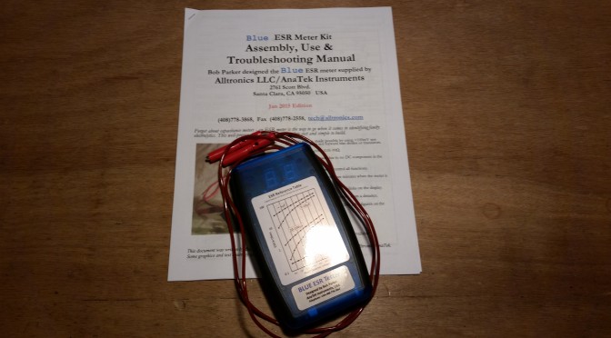
 Something great showed up in the post, a package from Anatek with the Blue ESR meter kit.
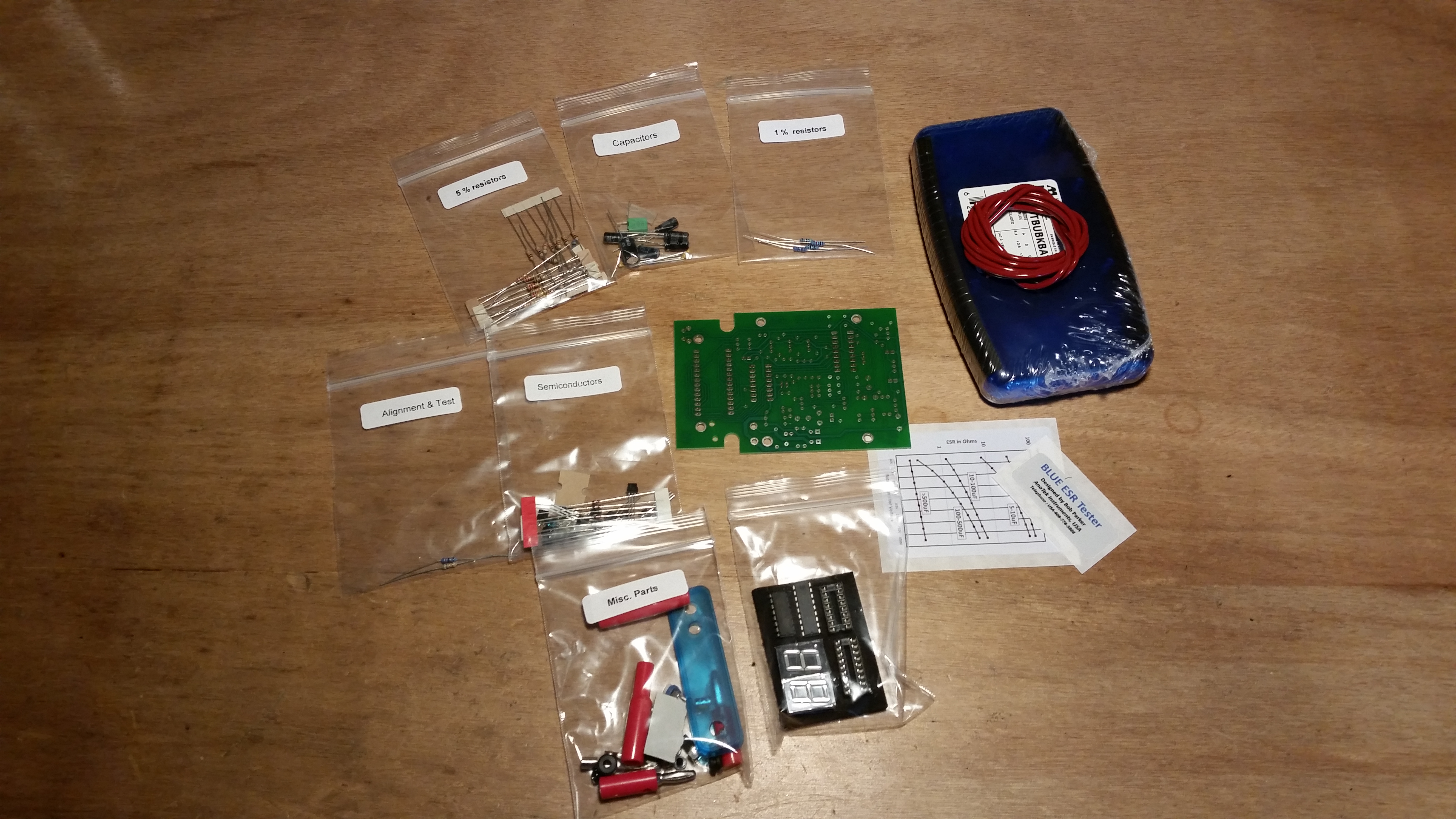 There aren’t a lot of parts, so the kit is fairly simple to assemble. The assembly order is based on parts types, first the 1% resistors, then the 5% resistors, followed by capacitors then semiconductors and so on.
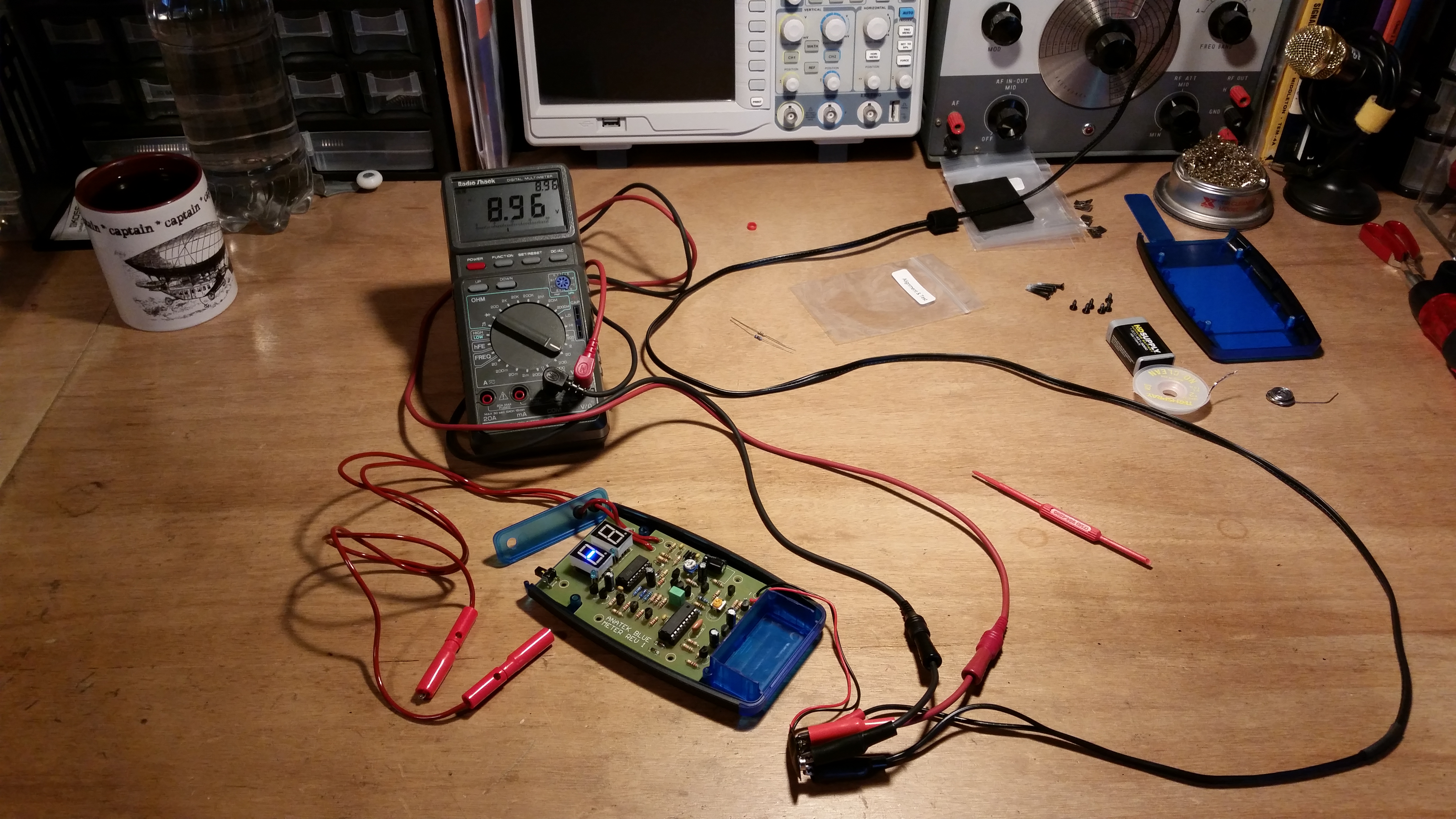 Once all of the parts are are on the board it’s time to calibrate the meter. Calibration is easiest if you have a variable power supply for testing the low battery indicator, but you can get away without one. The assembly instructions include a simple circuit you can build for this test.
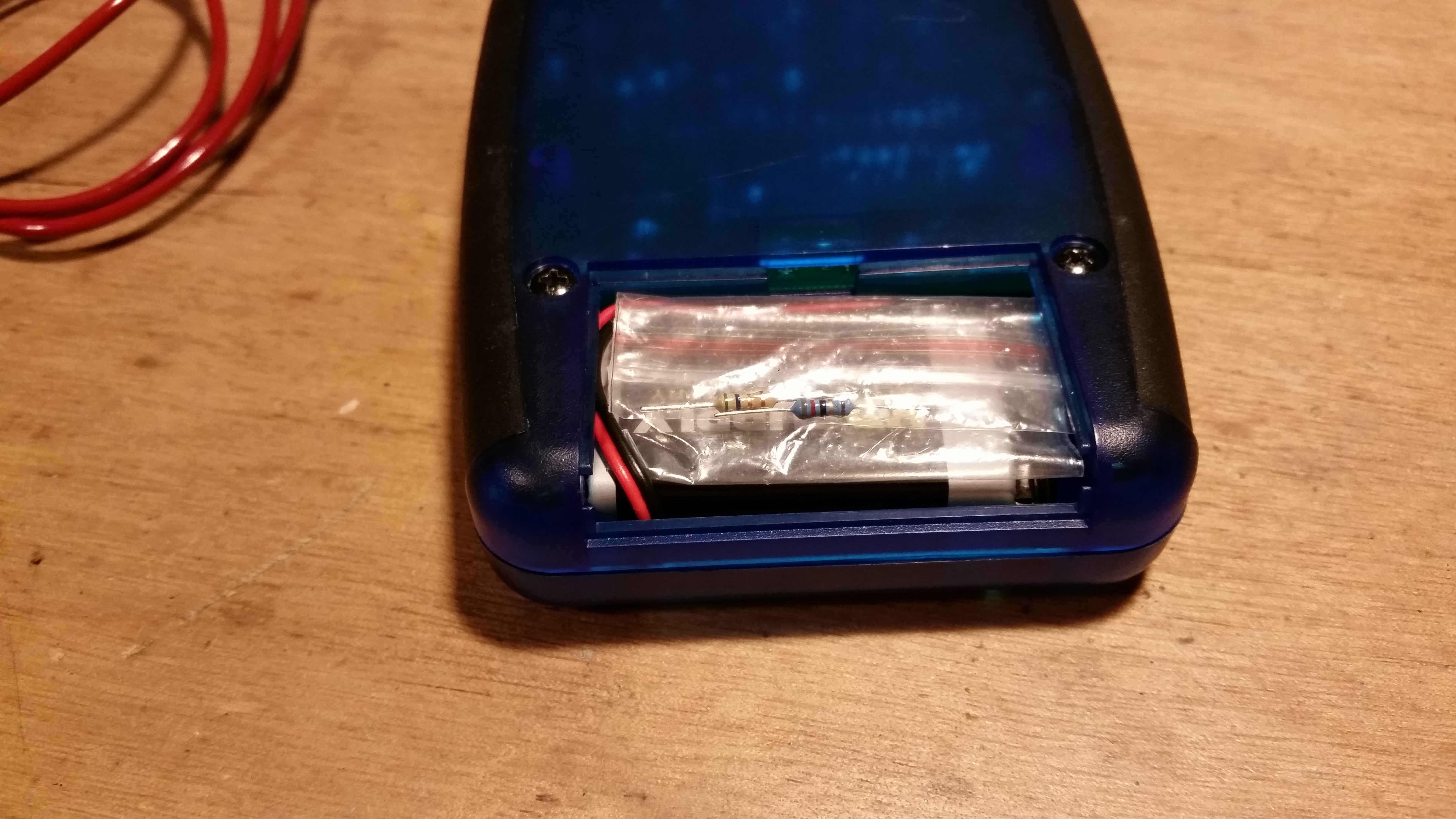 Calibrating the meter itself only requires the two resistors included with the kit for this purpose and the turning of two trim pots. I decided to take the calibration resistors and keep them stashed in the battery compartment for possible recalibration at a later date.
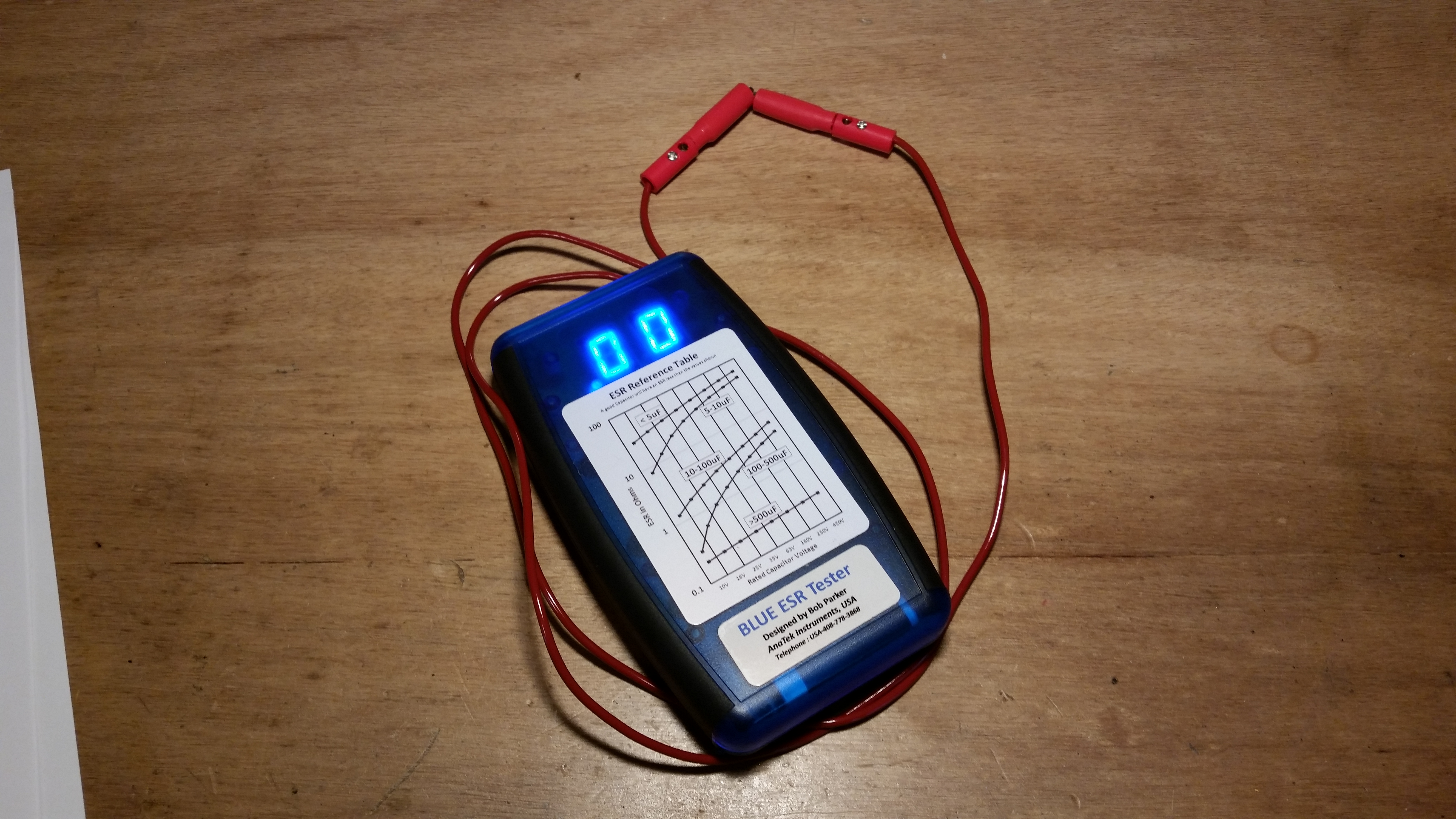 With everything calibrated and running well it’s time to button it all up. After buttoning it all up, it’s time to get back to that TV project.
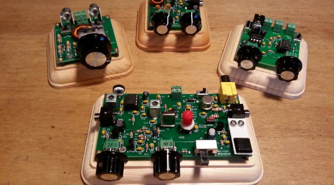
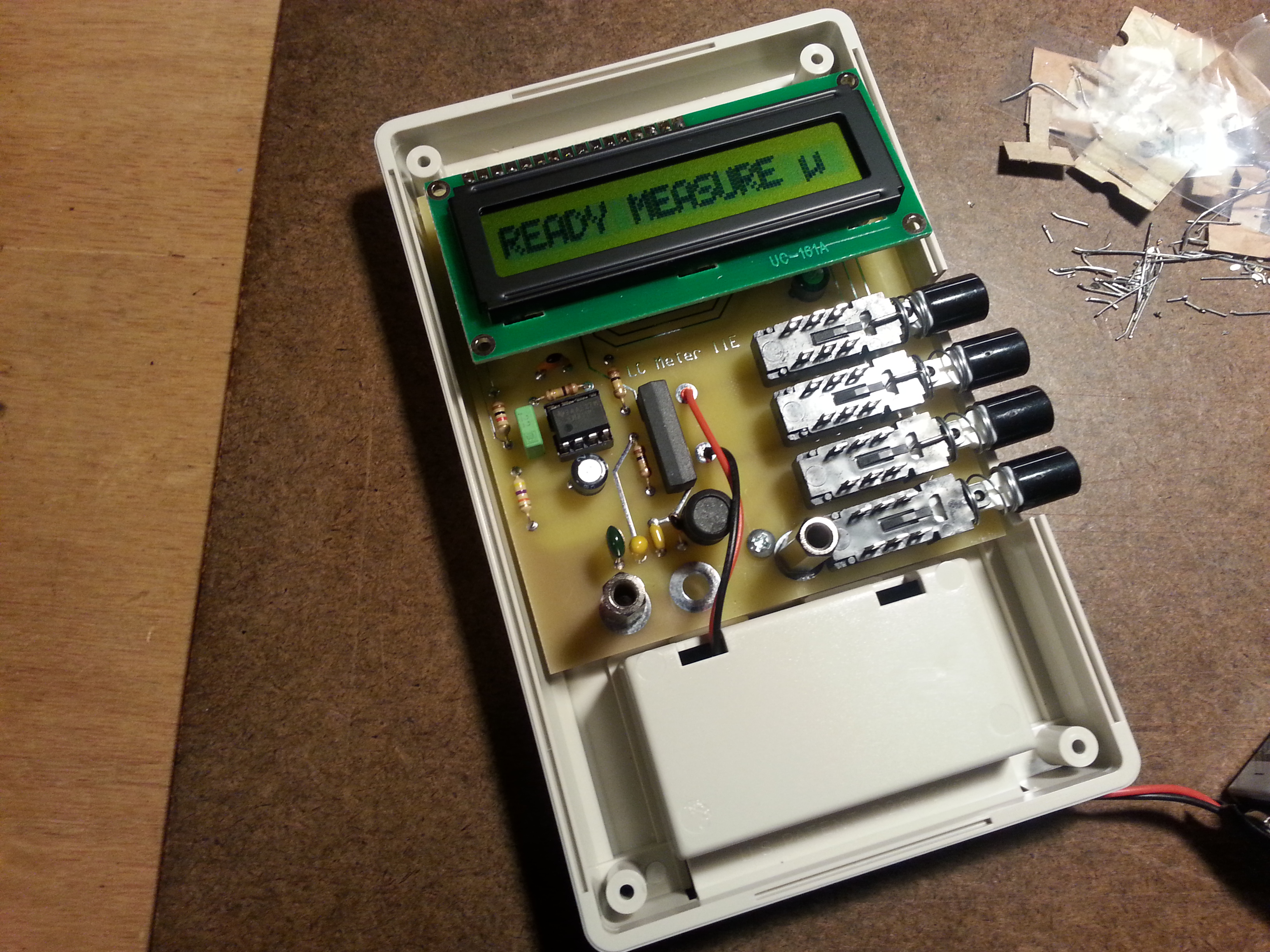


 e only hiccough was technician error. I got all of the components soldered in, mounted the board in the back of the case, mounted the LCD, and plugged in the battery. When I turned on the power switch I got nothing. I knew from reading the instructions
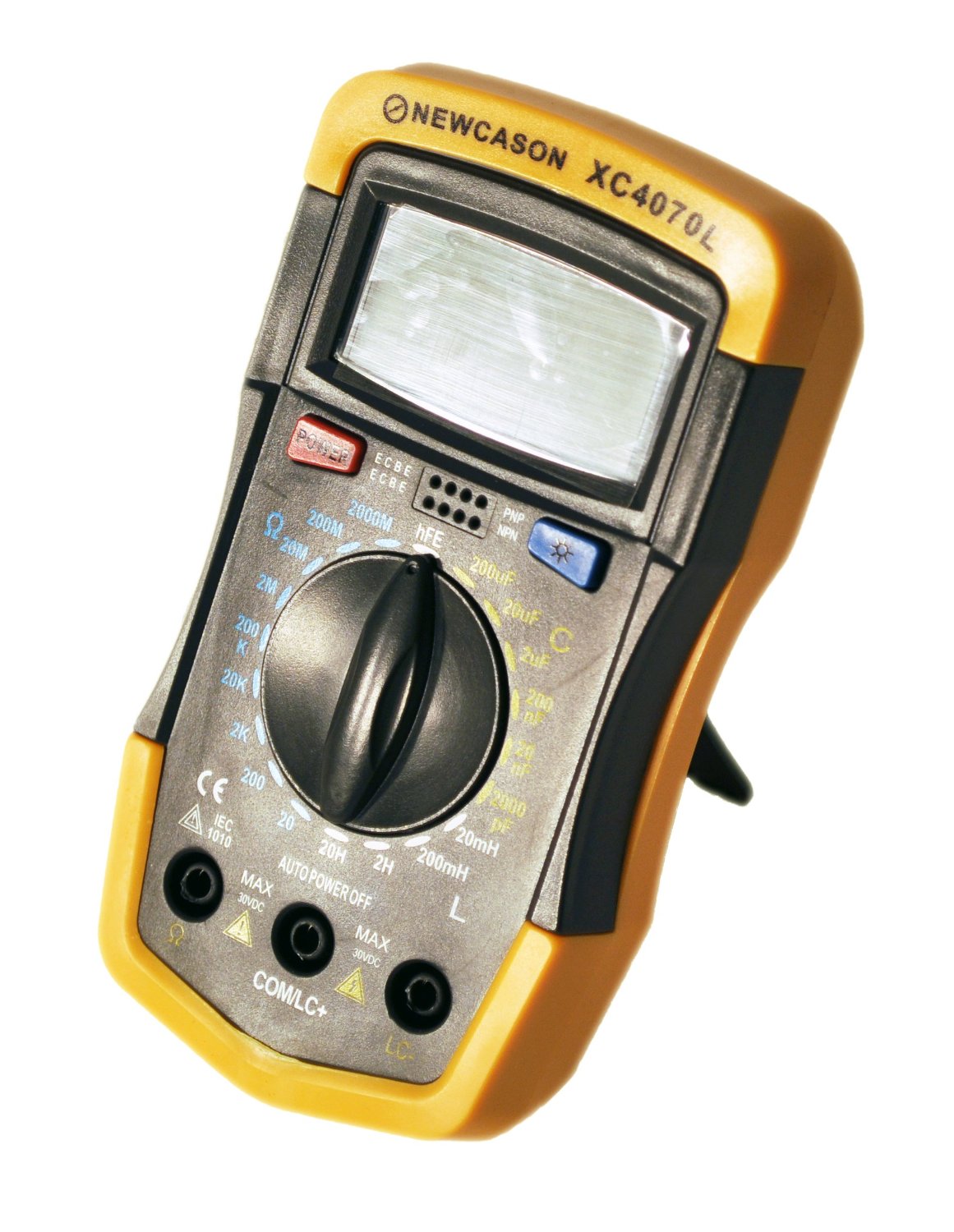


 The Newcason XC4070L Handheld LCR Meter I ordered showed up on Monday. Wow, what a disappointment. No stability in measurements whatsoever and I’m not talking bounce between two consecutive numbers. 32 ρF to 64 ρF on a 50 ρF capacitor which by the way I checked with another meter that pegged it at 49 ρF. This puppy is on the express return train.

 I have some tap and dies on order that I need to finish the 40 meter vertical antenna. I also have some parts in transit that I need to get started on the antenna tuner which is the next project on deck. As well as the project parts I ordered a couple of items for stock.