
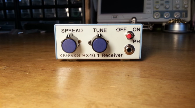
This project is the Direct Conversion receiver found in chapter one of Experimental Methods in RF Design. It is my first foray into the world of “ugly” or “dead bug” prototyping and I am starting it with no small measure of trepidation. The receiver is set up for the 40 meter ham band which is 7 to 7.3 MHz. Documentation in the book says the unit should receive 6.9 to 7.5 MHz. Once built I will be testing the unit for power consumption, frequency range, and frequency stability.
I have been looking over the design for several weeks rereading the text from the book and reviewing the schematic over and over again while gathering parts. Now that all of the parts are in hand, it’s time to jump on this.
Since this is a page rather than a post it will be a living document for the duration of the project build and testing.
The main unsettled issue at this time is the housing. Because of this, I am still not sure how all of the out-side interface points will be attached to the circuit(s) all but one, the power plug, are case mount devices. It will be changed to a case mount soon.
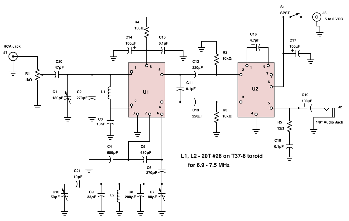
A couple of modifications to the schematic in this implementation are as follows:
- C1 is replaced with (2) 70pF trim caps in series for a total capacitance of 140pF
- C7 is replaced with a 60/140 varicap using both sides in parallel for a capacitance of 100pf
- C10 is replaced with a 60/140 varicap using only the 60pF side
2015-03-31
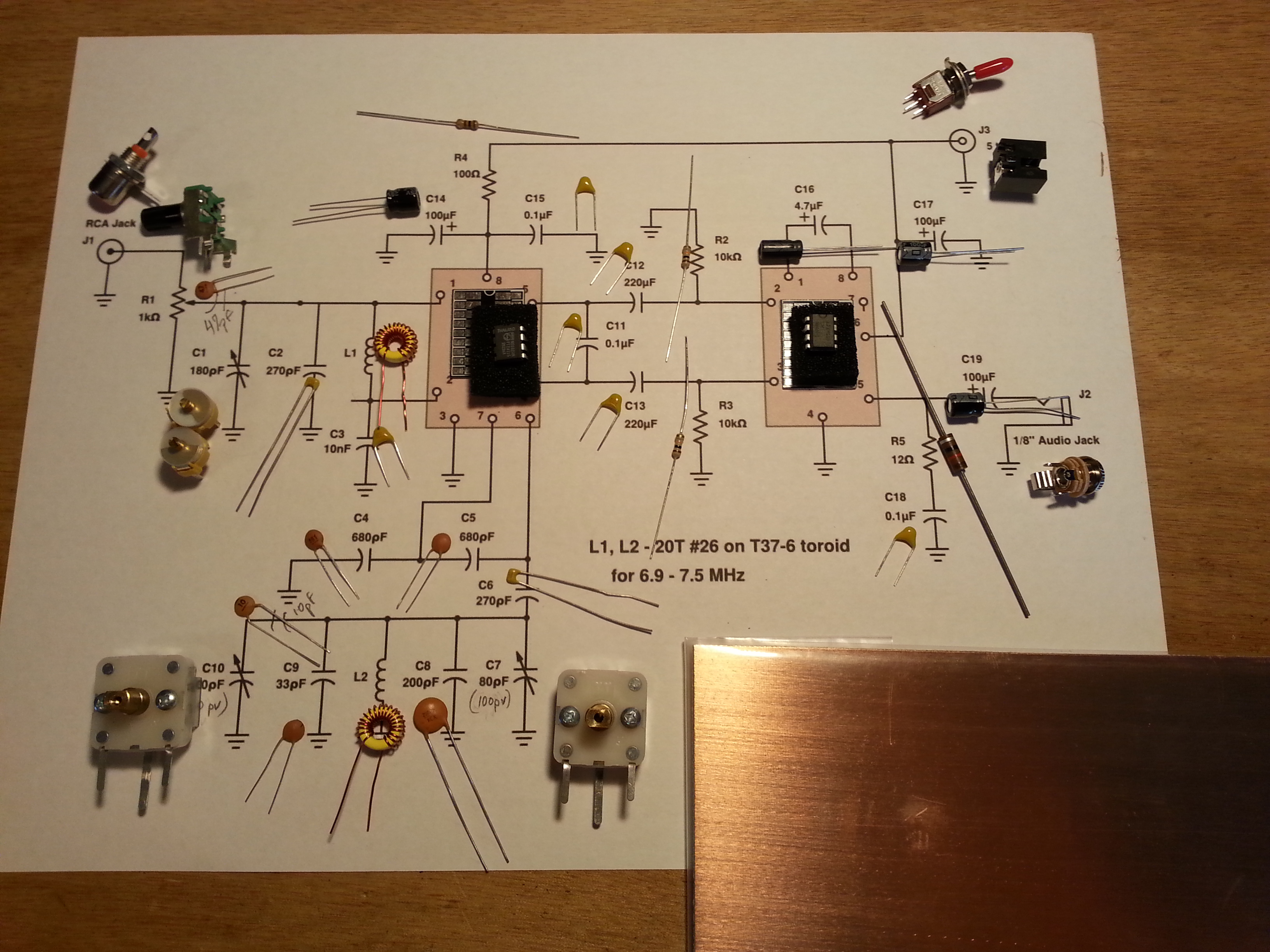
Generated a larger working diagram to use on the bench with the schematics.com online circuit drafting tool and laid out parts on schematic. I found a couple of component omissions, fixed the drawing and replaced the drawing here. (if there is a SW1, the drawing is the correct version)
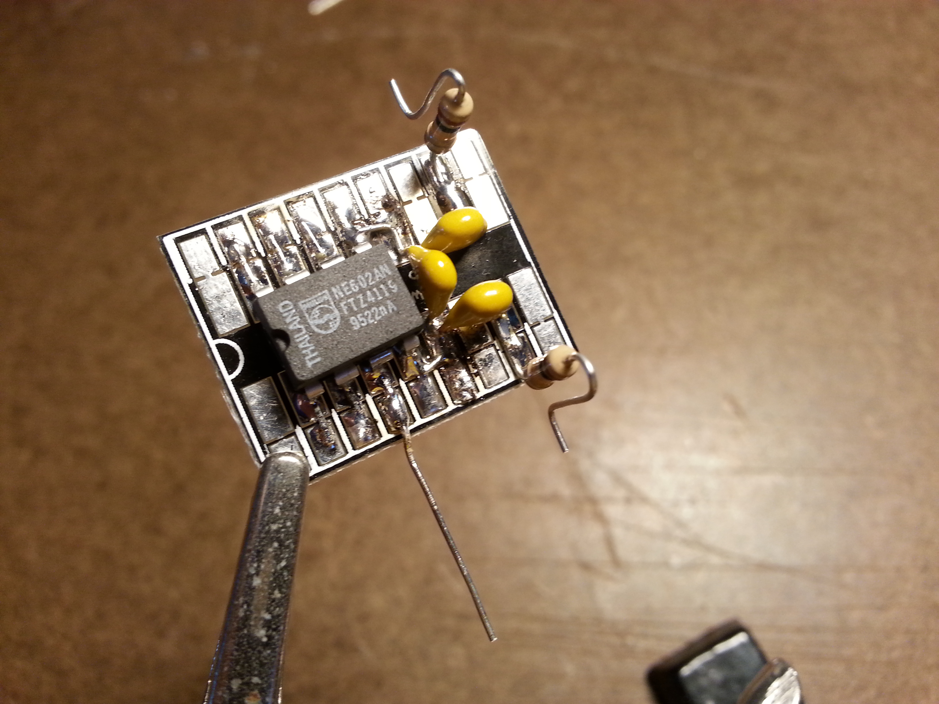
I have some surfboards from Rex W1REX at QRPme.com I figured I would use them for my first “ugly” project. Turns out they made getting started a lot easier. I started with tacking down the NE602 mixer/oscillator. What seemed most logical for the next step was the audio output buffer which fit onto the surfboard next to the 602.
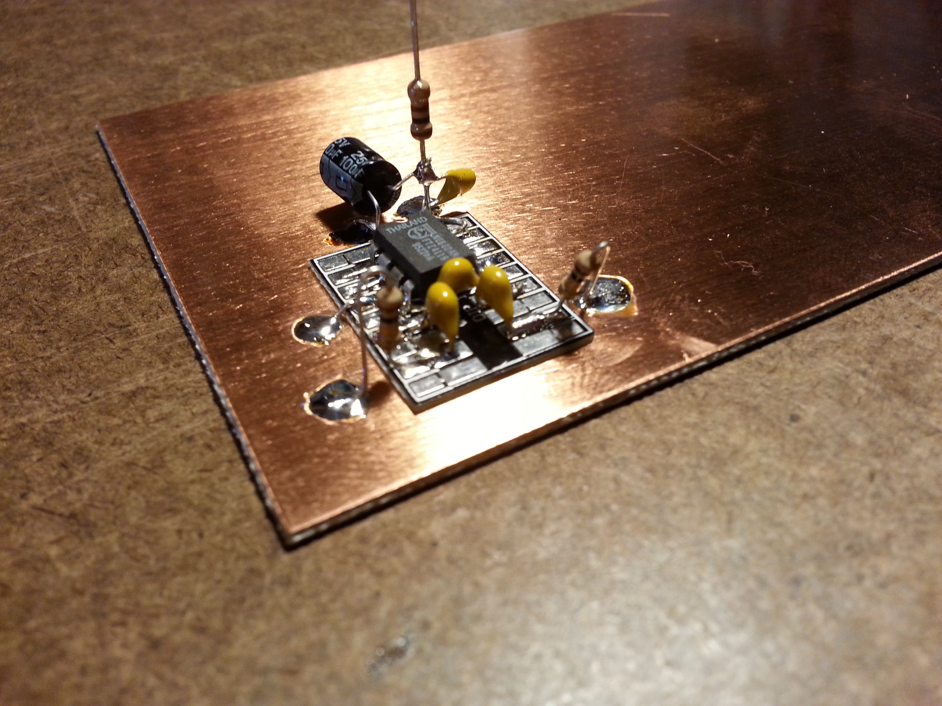
The next part of the circuit that also fit on the board was the power segment. With the resistor tied down and capacitors tied to the resistor there were 5 leads ready to be tied down to ground which also stabilized the surfboard down on the ground-plane.
The RF input and tuned circuit are next up on the slate for tomorrow.
2015-04-01
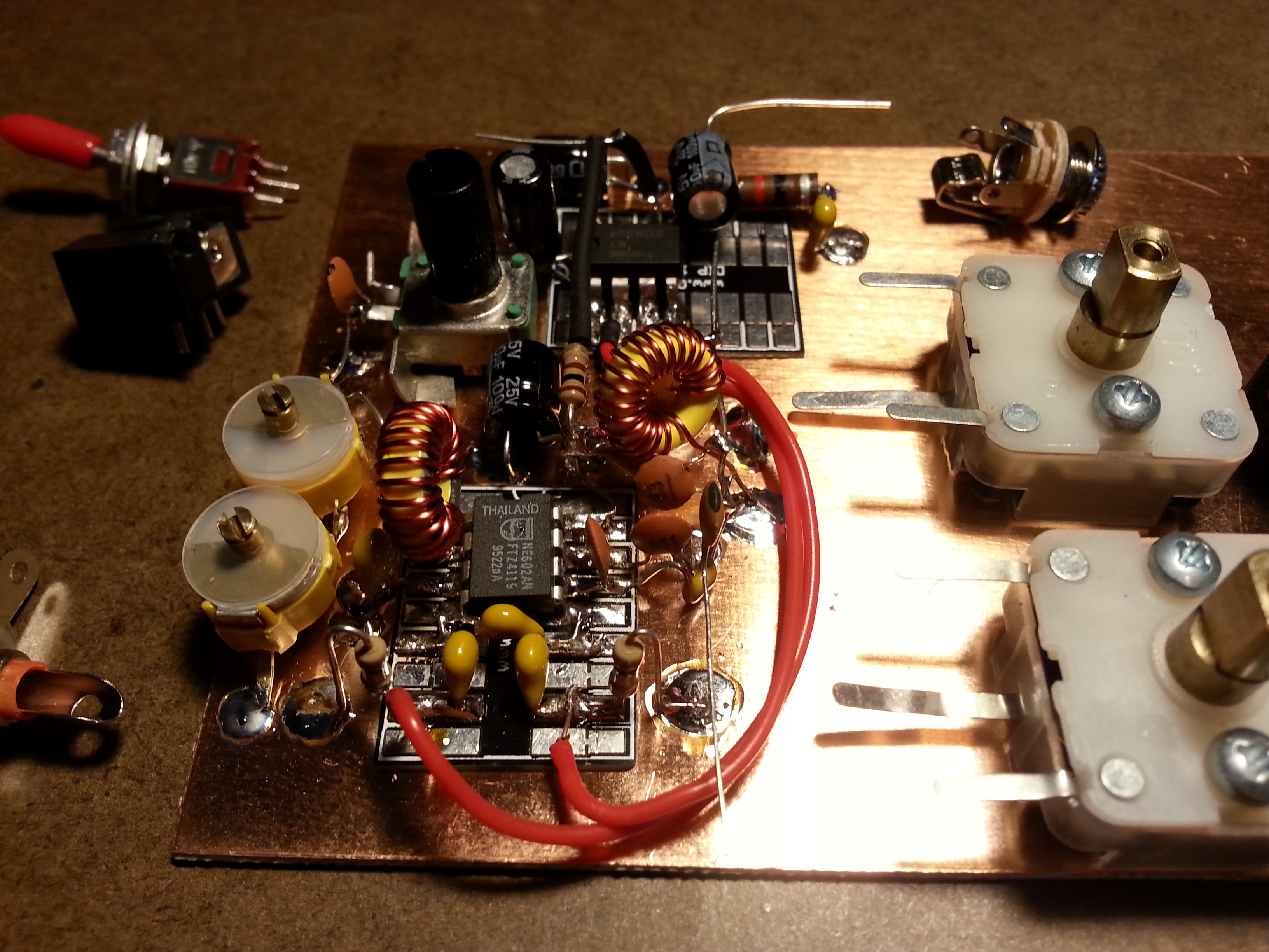
Big day today. Got lots of stuff done. First off the board got filled out nearly all the way. I filled n the audio board, top left, and got the feed tuning and gain portions done, left side. With the board filling out, the only things left were the case mount items.
With all of the components board mounted components tied it it was time to head over to HSC and pick up a case. I have aluminum suitable to make a case but I don’t have a break and I wanted this project to look good on the outside. I wasnt sure what I wanted but I knew I needed room for at least a 3″ x 3′ board. After looking around I found something that would work well, or at least I think it will.
This case gives me enough room for the receiver and the space to add a Rx/Tx switching circuit and a transmitter if I want to, and I think I will. Sorry for the blurry pic. It was more for scale anyway. Obviously one of my tasks today was to cut down the board. With everything on and an idea of where the case mount stuff would go I was able to chose the orientation of the board in the case and start planning the case mount components.
I drilled the standoff holes for the board and the holes for the varicaps. I still need to drill holes headphone jack and the power switch in the front and the holes for the power jack and antenna connection in the back. Once I get all of the holes drilled and dressed I will be able to make the last few connections and begin testing.
Procedurally I flubbed this project. I did not build each portion of the circuit and test it progressively as I probably should have. This will make testing and or troubleshooting considerably more difficult. Another area I may have overstepped my abilities is compactness. I know that many other builders spread things out more on prototypes. I am still a little hung up on keeping it “neat” even when doing it “ugly.” All-in-all I feel good about this project. We shall see tomorrow when I get it all tied together. If all goes well I may even be able to scan the band tomorrow night.
2015-04-02
I did a blog post that contains some of my thoughts on the project so far and possible mods to this design / project.

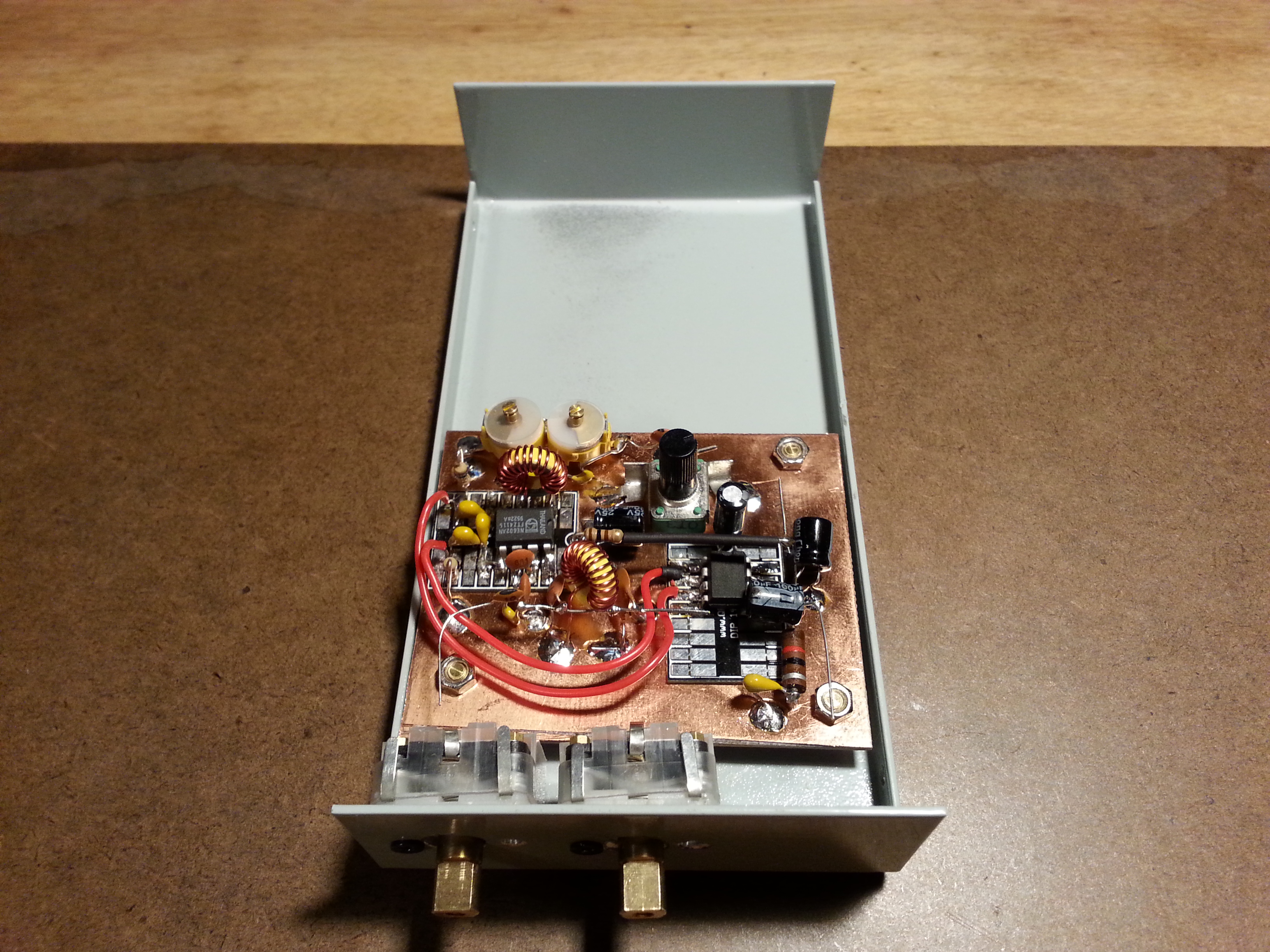
Finished drilling all of the holes and fitting the case devices. I also got all of the case devices connected to the board. After everything was tied together I thought it would be fun to take care of the aesthetics before plugging in the power and antenna.
All of the labels have been installed and everything is set for a test power up except for the power cord to the solar power unit. I hooked it up to the bench power supply and flipped the switch…
No smoke! The audio came up and the expected band noise was present. I did hear some faint voice transmissions deep in the band noise.
At this point I need a signal generator to be sure that the radio is in the band. I will need to test at several points in the band to be sure I am getting the full band range and ID some points on the tuning dial.
2015-04-03
I built a signal generator this morning. This one is only a single frequency generator but it will ball-park the band. More on testing to come.
2015-04-17
I was having some issues with the fixed frequency signal generator I built trying to use it on this receiver. Today I figured out why.

On Saturday the 11th I bought a signal generator because I really don’t have anything to celebrate the tools I am building against and I figured that would be a good idea. Besides, at some point I want to build a sig gen and I will need something to check it against.
Anyway, I spent time Sunday and today going through the sig gen to make sure everything was cleaned first, then powered up, smoke checked, and finally ops checked. All is well.
I decided to check the receiver against the new-to-me sig gen and was in for a surprise. The receiver is tuning in around 6.4 to 6.8 MHz not the expected 6.9 to 7.3. This does explain why I didn’t hear the 7.25 MHz single frequency generator I built.
On the plus side, it has the range to tune in the 40 meter band of 7.0 to 7.3 MHz. On the down side, now I need to go in and shift the frequency up. More to come I spect.
2015-04-19
Got the receiver tuned into the band with a few mods on the board today.
First off I tried tuning in the two 70 ρF trim caps in series that replaced the C1 variable capacitor (near the antenna jack). No real change in the tuning range. In fact not much of any effect when I removed it from the circuit to try various values, so I ended up just leaving it out.
In the description of the circuit there are comments on changing the number of turns on the L1 inductor in relation to the capacitance so I removed one turn with little effect. I removed two more turns and ended up with 6.4054 MHz to 6.8548 MHz, still not what I was looking for.
The L2 inductor has the same toroid, wire, and number of turns as the L1 inductor. I removed three turns from this inductor, which I should have thought about a little more. I ended out of band on the high side with 8.0064 MHz to 7.4785 MHz.
If I had removed one turn at a time I would have had to go through the process twice, but I wouldn’t have had to rewind the inductor. It would have saved a little extra work, but hey, thats what experimenting is all about right?
So if you are following along with the schematic, C1 is removed entirely, L1 is now 17 turns and L2 is 18 turns. The radio is now tuned in for 6.9021 MHz to 7.3713 MHz making it just about 100 kHz wider on both ends of the 40 meter amateur band which is 7.0 – 7.3 MHz.
Tonight I will be tuning around the band listening for some signals. During the week I will be trying to tune in to the W1AW broadcast signals.