Category Archives: Amature Radio

40 Meter Antenna: Thought Process

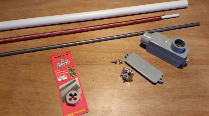
I picked up some hardware to connect the antenna bits together into one cohesive unit. Sometimes with hardware you have to just go to the store and look around for solutions to a specific problem or situation.

20150426_122414
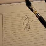
With this project I wanted to keep things as simple as possible and use off-the-shelf materials that are easily found and relatively cheap. One of the pieces I wanted was a simple piece of hardware I have seen many times. I have even bought it and used it, a three or four-inch long nut.  We used to use them for connecting CB antennas to rigid mounts with a nylon spacer block on the bottom and a bolt. The same basic format used to connect the spring mount base for mobile use. The intended use in this project is to connect the steel spike at the top of the antenna to the fiberglass body.

I remember buying these at Orchards Supply and Ace Hardware. I never had a problem finding one back in the 80s. Yesterday I went to OSH and Home Depot and the employees looked at me like I was from mars. They had these little 1-1.5 inch versions for connecting all-thread, which is what I am looking for, just longer. No clue. Nothing registered on their faces, even with the smaller version in my hand.

20150426_122018
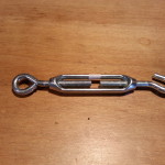
Anyway, the next closest thing was turnbuckle bodies. The “solid” bodies were aluminum and the open body type looked like nickel plate and galvanized. I ended up buying an open body style, but it really brought about several issues. First and foremost are the mechanical issues. The contact points on both ends are fairly small, less than half an inch. Even with the fiberglass rod and the steel spike screwed down all the way and touching there is still only a half inch of contact on either end.  These things are intended for stresses in tension not in bending which s what they will be exposed to in this application.

The next issue is the left-hand thread of one end of the turnbuckle. I was willing to deal with this I even started looking for a LH die to thread the fiberglass and this is where I decided to take a step back, reevaluate, and take stock of my options.

20150426_121813
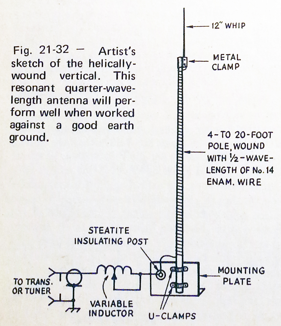
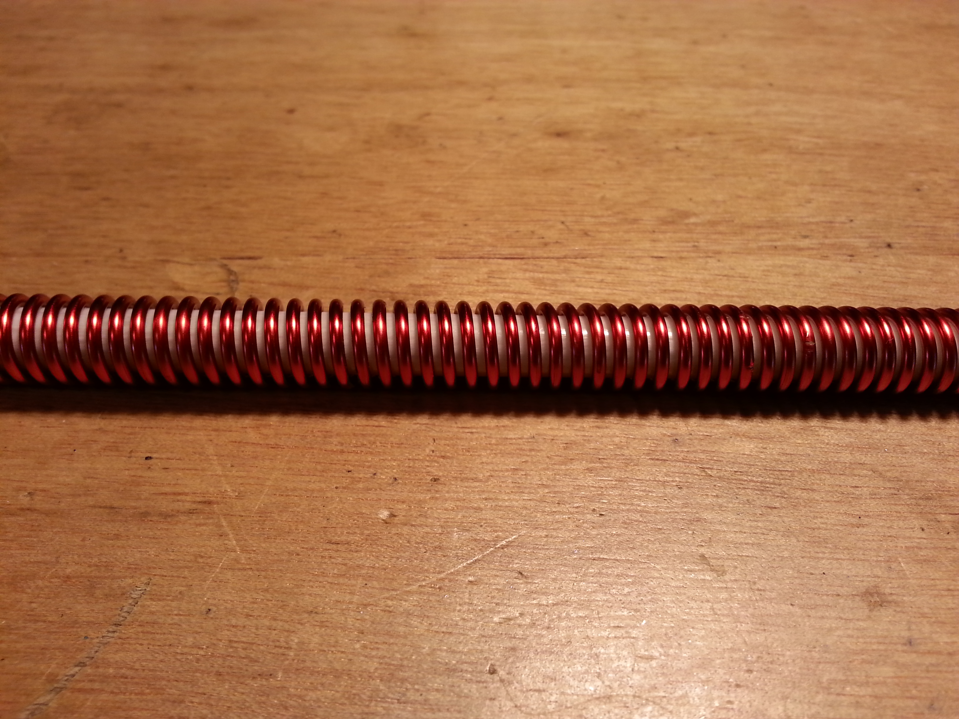
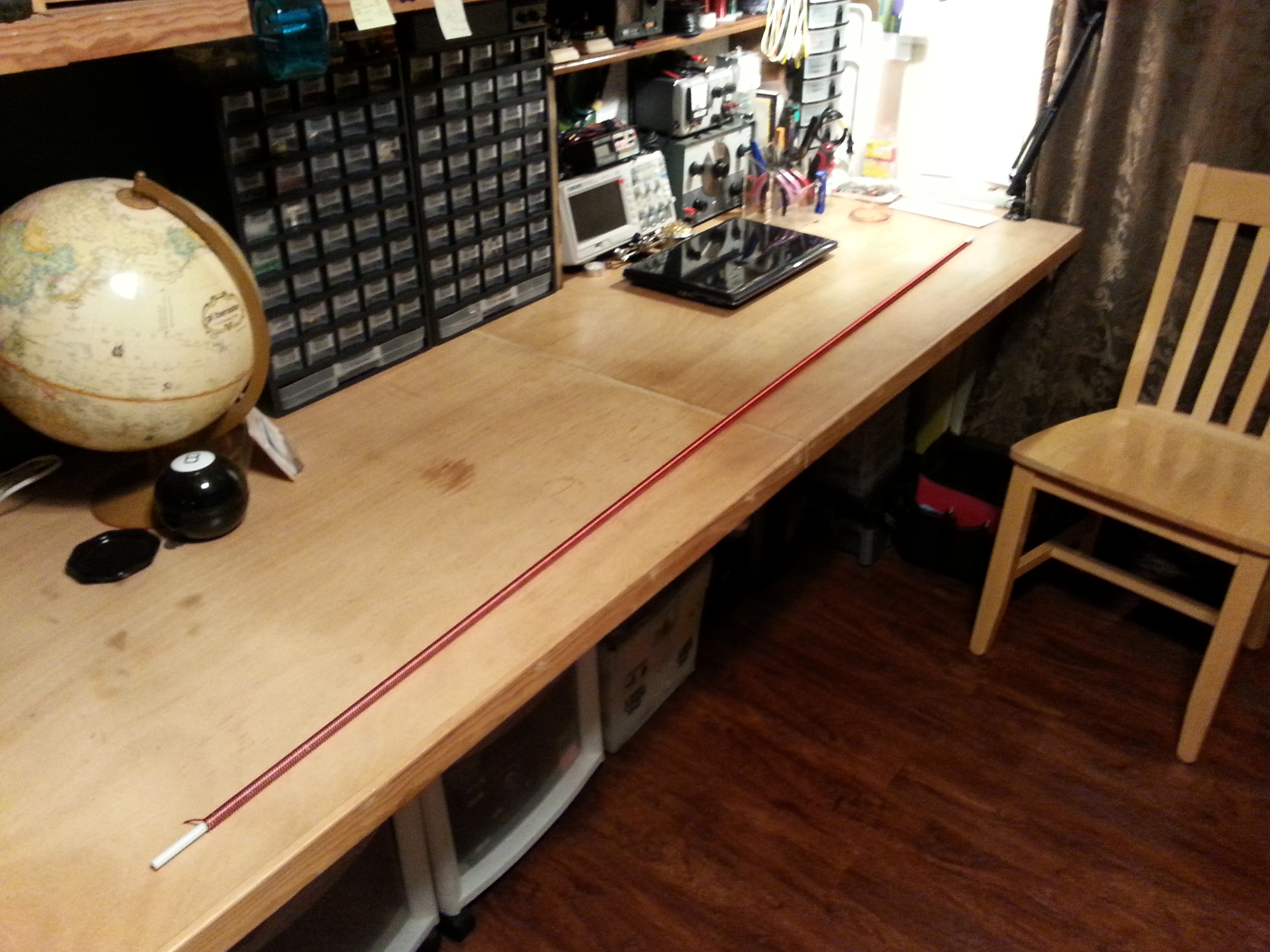
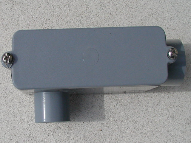
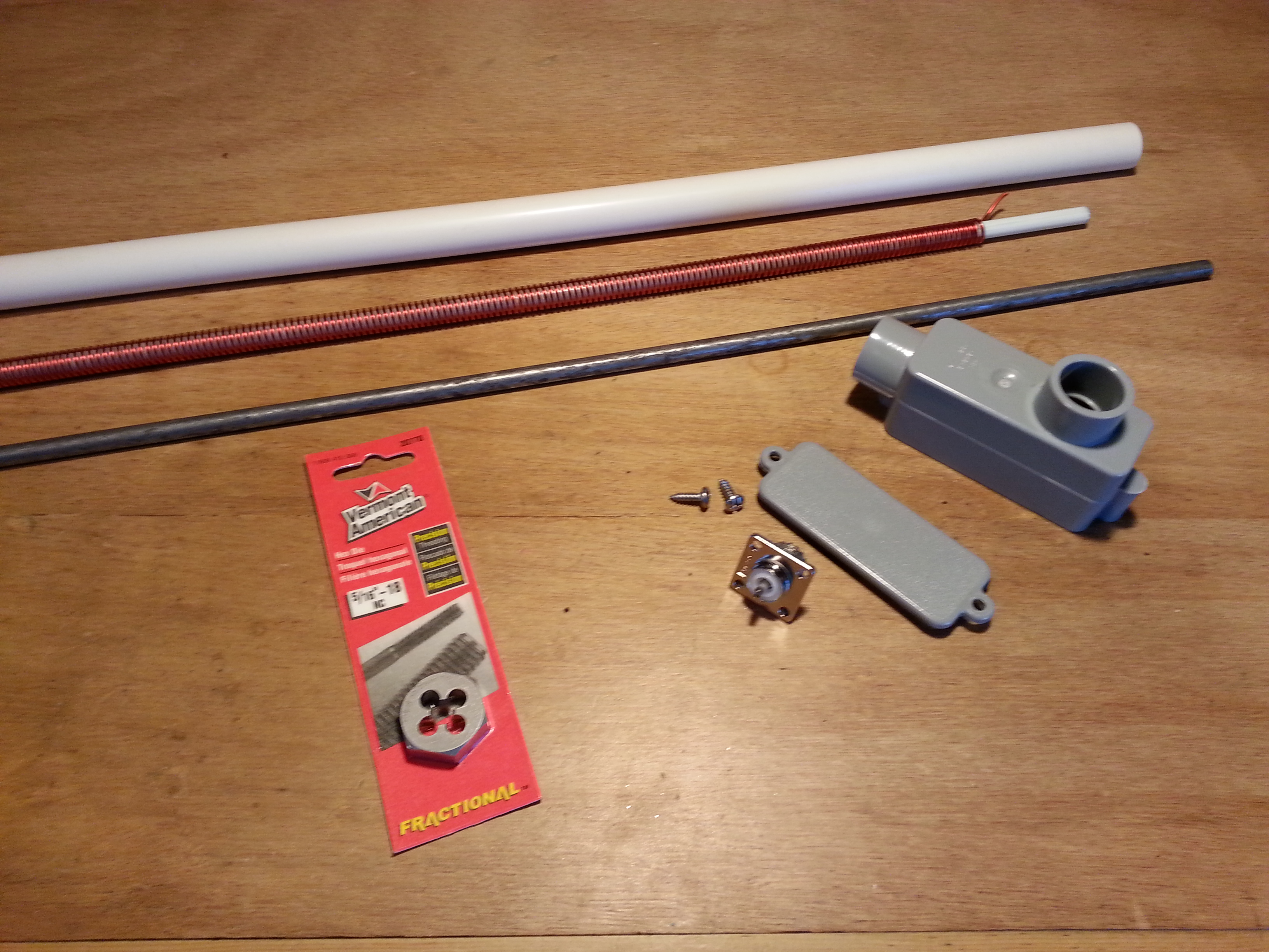
At this point the base end has been worked out. The right-angle conduit box is the base and will have 12 inches of half-inch PVC conduit inserted in the port that is parallel to the box. The wound fiberglass rod will be inserted through the PVC pipe into the base. I will cut off all but an eight-inch of the other port which will be the outside housing of the SO-239 which will be inserted from the inside of the box.

Once the antenna coil is soldered to the SO-239 on the inside of the box I will fill the box and the PVC pipe with polyester resin making the base a single solid weatherproof piece. The reason for the PVC pipe being 12 inches long  is to provide a solid place for mounting standoffs to be attached. All done with off the shelf hardware and materials with only one minor modification and no special tools.

Now back to the top end and mounting the steel spike to the fiberglass rod. The most direct method is using the all-thread nut I originally wanted to use. Since it is not available, and a sufficient replacement in size, complexity, and structural strength does not appear to be an off the shelf item, at least around here, I guess I need to make one.

I thought of welding nuts together and other welded configurations but they all require more work than what is really the simplest solution. Drill a piece of half-inch bar stock and tap it for 5/16″ 18 threads per inch. I already picked up the die, now I just need the tap and drill.

This solution does require a couple of tools, tap and die along with their respective handles, the right size drill (an F), and a little machining. This operation isn’t really a big deal. If you have a bench top drill press it will make things easier, but it can be done by hand with a bench vice.

The remaining decision is material for the threaded block. I know I have aluminum and I think I have both steel and brass that are the right size, or at least useable.  I am leaning towards the steel or brass. Aluminum and steel don’t play well together when there is the potential for moisture penetration between the surfaces making galvanic corrosion an issue as well as heat dissipation and mechanical contact issues.

More to come on this subject soon.

73,
~Jon KK6GXG

40 Meter Antenna

With the direct conversion receiver now working and tuned into the 40 meter band, it’s time to get to work on a better choice of antenna. The dipole would be great if it were in the proper environment, but this indoor, RF noisy environment is not conducive to picking up much.

Since tuning the receiver to the band I have been picking up both voice and cw transmissions but they are deep in the band noise. The other issue is portability. While the dipole can be pulled down and packed up for field use, it won’t work well in a mobile environment and would be a chore at home to pull down and put back up. So a whip makes the most sense for now. If the whip works at home I can wind up the dipole and keep it in the ready for field use.

Right now my focus is on getting the receiver, antenna, and any needed matching equipment in place. Once that is all together I can turn my attention to filters, amplifiers, and a transmitter.

Scan from the 1975 ARRL Handbook, page 606.

The antenna is a helically wound vertical that I mentioned in a previous post All Aboard the Project Train. I ordered a six foot fiberglass safety flag whip for the core and a fresh 1.5 pound spool of 14 AWG copper magnet wire to get the project going.

Yesterday I started the antenna construction by unrolling the 66.5 feet of copper wire and marking it every five feet, mostly so I didn’t lose my count. After dinner I started winding the coil onto the fiberglass in a tight coil. The picture in the header for this post is the fiberglass with about 30 feet wound on.

20150422_093128
66.5′ of 14 AWG copper wound onto a6′ x 3/8″ fiberglass rod

After winding the rest of the wire onto the fiberglass I threaded a dentists tool in between the wire wraps up the full length of the rod to create the uniform spacing for the coil.

On reflection at this point I think I might have opted for an 8 or 10 foot rod. For most applications it might be a better choice but neither would fit well indoors so 6 foot it is. I may build another antenna like this if it works well and try different lengths and diameters for different applications. A 10 foot whip would be better with a 1/2″ core and any longer would need 3/4″ or 1″ to remain stable unless it were placed inside a tube and filled with epoxy resin, another option. I haven’t tested any of these, I’m just spitballing with the structural integrity issue and weather resistance.

20150421_220832Now that the coil is done, the most difficult and time consuming part I think, it is time to move on to the spike and the base.

The plan for the spike is to pick up a small piece of 3/8″ copper tubing about 4″ long and use a coax crimping tool to mechanically center and attach a 1/4″ steel rod to about 2″ then sweat solder it together. After the spike is properly affixed, scoot the coil up a bit and solder the copper wire to the tube, add some epoxy inside the tube and scoot it back onto the fiberglass rod. This should give plenty of mechanical stability to both the spike and the rod as well as a good electrical contact. To help prevent galvanic corrosion I will coat the steel/copper interface with a few coats of lacquer.

The base is where I am going to have to think some more. The diagram calls for a variable inductor at the base of the antenna. I don’t think I will need this because I am planning on using an adapted Z-Match antenna tuning unit from chapter 23 of QRP Basics but that is for the next project.

OLYMPUS DIGITAL CAMERAIn the mean time I am thinking about using a PVC/ABS 90º conduit fitting with an access panel, cutting off and sealing up the right angle (on the bottom of the image), inserting the bottom of the antenna with the wire sticking up out of the box a little and filling the cavity with epoxy resin, leaving enough room to install an exterior lug fitting to attach the wire to on the inside.  For mechanical stability and to provide a secure mounting point I was thinking about using 6″ of conduit around the antenna and filling that with epoxy resin as well.

I hope to get the spike done this week and the base over the weekend. While out and about getting the final parts for the antenna I will be hitting HSC for the parts for the Z-Match. Another busy week for radio. 🙂

73,
~Jon KK6GXG

All Aboard the Project Train

Sometimes it is indeed a project train, not just a project; occasionally a train wreck, but it’s early so we’ll hope for the best.

Now that I have built several receivers and a transmitter for 40 meters, I probably should have an antenna that does more than pick up all the RF noise around the shack. The antenna, and I use the word loosely, is nothing more than a dipole of 26 AWG insulated wire strung around the house. While it might work well if the wire was straightened out on a hill top, or even in a backyard, elevated 15 feet or more above ground, in its current incarnation, in a word, it sucks.

Next up on the project block, an antenna, sort of…

I have been looking at several small footprint antenna options like spiral coils that look like those God’s Eye yarn and popsicle stick things you may have made as a kid,  the one in the movies from the 40s when the resistance spy transmitting Nazi secrets and the SS storms in. It looks like a X and has thin wire wound around it.
288And Small Loop antennas that look more like old direction finding antennas on aircraft. And by the way, according to the formulas and general information, for 40 meters, not so small, 10′ diameter.

Now there are lots of variations and tons of experimental configurations to run with, and I do want to play with many of the possible configurations, but I need a stable, small, portable option for the immediate future. Something I could mount on the car, throw up on a pole, or stand up on the back porch, all without much effort. I also need to keep the cost down.

Scan from the 1975 ARRL Handbook, page 606.

Enter the Helically-Wound Short Vertical. I ordered some 14 AWG lacquered copper magnet wire and a 72″ long 5/8″ diameter fiberglass rod, I need to learn to make these so I also ordered a How-To book on making composite fishing rods, and I’m in $20 so far. I have all of the hardware items including the 12″ spike for the top. What I don’t have is the variable inductor, or a tuner.

Whooooo Whooooo! Here comes the train.

RollspuleLets start with the one I haven’t done any research on yet, the variable inductor. The mechanics are fairly simple, rotate the coil and the follower moves up and down the coil creating a tap point. As long as the coil is perfectly cylindrical, the follower makes good contact, and smoothly moves down its axis rod, no sweat. he he he, no sweat I only need the one variable inductor according to the diagram so I really need to find out what value I need. I already have several small value iron-core variable inductors so I may not need to make this one, but if I do, it will be a homebrew. These things are a high-dollar item otherwise.

Moving on to the antenna matching unit. I have plans for one that is fairly simple and straightforward, I even have most of the parts on hand. What I don’t have is the variable capacitors. Sensing a theme here? Variable…

cav-167-205-71_lgBA funny coinky-dink on capacitors; while I was doing research on the Small Loop antennas I came across several websites that went into some lengthy discussions on making variable caps. Turns out, they aren’t that hard to make, I even have nearly all of the materials to make several. Not only are they fairly easy to make, but the formulas for calculating the capacitance based on the area of the plates, number of plates, and the distance between the plates is also fairly straight forward.

So lets see where we are now…
I have three receiver and one transmitter for 40 meters. There is an antenna for them, but it sucks particularly in this location. My next project is to build another transmitter, But I will need a better antenna first…

  1. Antenna
  2. Resonator for antenna (variable inductor)
  3. Antenna tuner
  4. Variable capacitors for the tuner

Now, after these are done I can move on to the new transmitter. As a side note, with the next transmitter project I wanted to pump up the power all the way to a couple of watts, not just miliwatting it. I also want to include SSB (Single SideBand, voice) as well as CW so I can incorporate digital modes into the shack. For all of this the antenna really needs to be better than what I am using.

That’s all for now, 73,
~Jon KK6GXG

40 Meter Loose End

20150410_115049Today just started off good. The post came early and an expected package came a few days early, my QSL card order from Vistprint.

I’m not quite sure when I will need to send any out, but now I have them and I am very happy with how they came out. I’m also very proud of them, I spent the better part of a day working on the layout and confirming the text-safe areas around the card. The finish product is just what I was hoping for.

20150408_154753A couple of days ago I got a package in the post from another ham, Brad  (AA1IP) and oh my, what a box it was. A medium sized  USPS Priority Mail box filled to the top with stuff.

I started sorting it out that evening and last night and again this morning. Its all sorted into like or similar components. There is still a lot of sorting to do, particularly with resistors and capacitors. Among the jumble there were a few packets of resistors already sorted by value and those are my project for tonight. Get them all stowed away.

20150408_162644The sorting process will take a while and I’m in no rush, so bag by bag over time it will all find homes. Once I get everything stowed I may ask for another. Mmmm, a masochist, I am *in my best Yoda voice*.

A small follow up project got completed over lunch today. I finally finished the power cable for the 40 meter receiver I built. The original plan was to build the receiver and a follow up transmitter, package them together, and power them both with a solar charger / battery pack. Also in the original plan was to build out the cable from scratch.

Funny thing about plans… I dont have any good multi-conductor cable anymore. The closest I have is some cat 5 and some twisted-pair for telco work. Nether is appropriate for this project. I was waiting to go to the Electronics Flea Market @ DeAnza this weekend but I also have plans to go to a radio builders club meeting on Sunday and check things out there. I was encouraged to bring my project along, and since the build was complete I thought I should power it as planned.

20150410_132528Long story short, I know, too late, I decided to pull an extra USB printer cable out of my computer junk box and use an existing cable, clip an end, and install the power plug. Easy peasy.  The plug isn’t quite big enough for the cable but I adapted it and heat shrunk that end for some extra stability. Thoroughly checked it for shorts and opens twisting it about and we are good to go.

The radio can now be powered by a computer, USB car adapter, or the solar power supply I had originally intended to use. Any standard USB source with the appropriate 5 volts will do.

I’m sure I’ll have more to post about after the Flea and the club meeting.

Until then, 73,
~Jon KK6GXG


Radio Goals

I tend to view “goals” as an intermediary point, even a starting point in many cases. They are rarely endpoints, and when they are it’s usually only an end in an administrative sense, like earning my Amateur Extra license. Administratively I reached an endpoint because it is the highest level in the Amateur Service, but in reality it’s a beginning. There is so much to learn that requires I earn the license first.

My current goals in radio are much the same. They are the getting-to-the-starting-line kinds of goals. I started studying for my commercial radio license shortly after I earned my amateur Technician class license. Well, that is to say I bought the study guide and began reading it. I also purchased some test prep software. While I have been poking at it off and on, I hadn’t made any serious efforts to study until this week.

Earning the GROL (General Radio Operators License) has been a goal since I started studying for my Technician, I just hadn’t set a hard date for it. I am still refining the hard date, but it will be this year before the end of June. I also have a goal to get the RADAR endorsement added to the GROL license, this year.

Another goal is to get on-the-air using CW (Morse Code) at 10-15 wpm (words per minute) by the end of the year. This is most definitely a starting point. It is the lead in to getting my commercial Radiotelegraph license.

GROL and RADAR are personal goals that also have a pragmatic side. With these licenses I am authorized to work on most marine and aviation radios and RADAR. This includes mobile (in the craft) and land based comm, RADAR, and navigation radios. A big boon for the aviation pilot/mechanic/instructor. This also opens up some doors in the commercial and government radio services.

Learning CW is purely personal. The CW requirement for an amatuer radio licenses went away entirely in 2007 but it was one of the factors that kept me away from ham for 30 years. Now that it is gone from amateur radio requirements my only way to concor that obstacle is to learn it, practice it, become proficient in it, and get the only class of license that still requires it; a commercial Radiotelegraph license.

The Radiotelegraph license process has four components, two written test elements, one of which I will have already passed with my GROL, and two code test elements. The code tests are 16 code groups per minute, and 20 wpm at 100% copy accuracy.

Like some other commercial licenses there used to be different classes of license, now there is only one radiotelegraph license and this consolidation happened relatively recently. I want to be sure and do this before the class goes away altogether; so my goal for this license is to take the code exam elements before the end of summer 2016. This should give me plenty of time to build speed and proficiency.

Fortunately the amateure radio service has lots of room for code practice and plenty of cw hams to keep practicing and improving the skill. I am looking forward to learning the code well enough to get on the air soon!

73,
~Jon KK6GXG

Fresh Prespective

Over the last few days I have been working on a direct conversion receiver project I found in the book Experimental Methods of RF Design last month. I had been planning and even started a very similar design back in February. I was having problems with that project so I picked up the EMRFD book to help figure out what the issue was.

EMRFD-40m-ReceiverThere in the first chapter was this design and I decided to scrap the other project and started working on this one.  It wasn’t like “oooo, a new shiney…” because they are very similar designs and the goal was to build a direct conversion receiver for 40 meters, not specifically that receiver.

Now that I have finished unnecessarily defending my position on hitting the reset button on the project, we can continue.

This time I decided to go with the “ugly” method of prototyping. I was not aware of the induction issues with the plastic pinboards or the other problems that can arise with high-speed or precision circuits. I had seen a few things on ugly construction and comments on its superiority over the plastic breadboards, along with other similar prototyping methods like “Manhattan.”

Since I had never done ugly before I was a bit nervous about it. I have used perfboard successfully on other projects and while perfboard does not have the same negatives as pinboards, it doesn’t have a ground plane ether. This can be problematic in RF circuits.

Any hoo. Yesterday I finished soldering the board and started mounting stuff. The project is screaming along and I have been pulling back regularly to make sure I don’t rush to finish. I have been going back an checking the new additions for physical problems, shorts, cold soldering, and the like. So far things have gone nicely.

20150401_193337This morning I sat down and looked at the partially mounted project box and some things crossed my mind. If I only put an antenna port on the back, instead of including a power port, I could actually have an internal battery pack. I could even add the power port and include a charging circuit for the internal battery…

I nixed this idea on this build because I intended to use a battery pack / solar charger that I already have so the power possibilities will be saved for later.

I do plan on adding a transmitter to this case. This brought my attention to the front panel. I am installing a power switch and headphone jack for the receiver, but I would need a jack for the cw key and a TX/RX switch. I could fit both of these components in the front panel integrated with the receiver parts without a problem. I could even install them now to prepare for the inevitable. I even have the parts in stock.

What I didn’t think about last night was the tuning of the transmitter. I don’t have the room for the tuning components on the front panel. I don’t know if I could modify this oscillator/mixer to work in conjunction with a transmitter thus converting the whole thing into a transceiver. I will have to get back to the book and read on.

In all honesty there are a couple of other things too. I would want a beat oscillator which would need a momentary switch and some other logistical elements to think about as well.

I spent a lot of thought on keeping this board small. I didn’t want to crowd things too much, but I wanted a small planform. I got what I wanted and I learned a few things about experimental design.

Planning ahead is not just about where the rest of this circuit is going. It includes thinking about the likely evolution of the project. Would I convert this project to a transceiver? Probably not. I would more likely build a new project ether from a different design already established, or take a lot of time and build modular circuit clusters testing them as individual units and working out the logistics of placement, interfaces, and housing configurations as the project developed.

I am actually surprised at how much I have learned from building this little DC RX, and I’m not even finished with it yet!

73,
~Jon KK6GXG

Lab Book Conundrum

I have been doing a fair amount of homebrew electronics projects as of late and I am coming to a point where I need to address documentation. With my woodworking projects I really don’t worry too much about documentation. Some projects don’t even have plans beyond a couple of dimensions on a post-it note.  Electronics projects are a bit different.

So far my projects have been taken from articles online, from magazines, and from books. I have kept hard copy of the designs for the most part, and any changes or additions I may have made have been noted on the hard-copy or attached as separate sheets.

Now that I am delving into the world of bigger projects and doing tests of the circuits beyond continuity at various stages in the build I should be keeping more in depth notes with test results and the like. The question is in what form should these note be. There are so many options that I’m just not sure which route to go.

DigitalDelemaThe obvious choice is an electronic notebook. I use OneNote currently and have used Evernote in the past. A part of me is a bit paranoid about data loss, so exclusively electronic notes make me uncomfortable.

I do regular backups and I keep redundant sets of data, but there is always the contingency you didn’t or couldn’t prepare for. There is also something to be said for Long Now thinking when it comes to data storage. I have come across a lot of stored data in formats and on hardware that are now very difficult to retrieve and if you manage to get the data out, the big question is will it be complete.

Any body remember 5¼” floppy discs? How about 10″ floppies and 8-track tapes?

This of course leads me to a hybrid solution. Digital notes occasionally printed out to hard copy and kept in binders.  It’s not like I’m doing any cutting edge work or something involving national security, but if I have learned nothing else in life, I have learned this, you never know where things will lead or when you will need information you have gathered. Data hoarder, maybe.

How long is long?
How long is long? This book is over 100 years old.

One definite advantage to digital notes is the ease in which that data may be shared. Another is the ease in searching through pages upon pages of notes for a specific piece of information. How about the ease in linking to other resources rather than copying that data, though this is a double edged sword. If data is not long-tail, it may not remain at its current location for very long. How long is long anyway? There is also the typographical concideration; typed notes are much more legible, by my hand anyway, than handwriting or printing.

Time for a little more research and thinking, the clock is ticking …

73,
~Jon KK6GXG

CW Practice Oscillator

Mark I – Transistor Based Oscillator

Mark I protoboard and schematic

(2015-04-03 This page has been copied to projects)

This was the first attempt at an oscillator for practicing CW. I don’t remember where I found this particular schematic but there are a ton of oscillator circuit designs available online.  Click here for a Google search that will result in a lot of options (over a half million hits!) The image results are a good place to start.

I committed to protoboarding this design because I wanted to play around with it some more. At the time I built it I was planning on getting an O-Scope but I didn’t have one yet.  Now that I have one I can revisit the circuit.

Mark I Oscillator - simple to build and only a few components. Not real stable though.
Mark I Oscillator – simple to build and only a few components. Not real stable though.

The AF (Audio Frequency) tone is unstable to say the least. It varies from 3kHz to about 200Hz . The wave form resembles a square wave, but only loosely.  It is very spiky and irregular.

While this is a simple circuit to build, uses only a few components, can be built very inexpensively, was a fun basic electronics project, and would be good as a beginners circuit / soldering project, I wouldn’t plan on using it for much more.

I would avoid it for a CW practice oscillator. If you are serious about learning CW, do it with a stable oscillator that will be pleasant to listen to. This thing can squeal at times.

Mark II – 555 IC Based Oscillator

The 555 IC oscillator is much more stable than the transistor based one

As the section title above says, this oscillator is based on the 555 timer integrated circuit, a much more stable oscillator, also with few parts.

I documented the build on Flickr but the focus was more on the cabinet build and less on the electronics.

This circuit makes a good CW practice oscillator. Still a very easy build for beginners and fun. I was going for a steampunk look with the cabinet build. There are many things I think I would do differently in the cabinet build to make it easier, and smaller, but the oscillator works just fine as is.

The waveform is a pritty clean and produces a consistent 724.8 – 725.2 Hz tone. This circuit does consume more energy then the other. I put a fresh battery in the oscillator, had done a week of cw practice 20 minutes a day when life called and shelved it in May 2014. I just took it down and did some testing when the battery died.

Thing two I might change, a positive power cut off switch to completely lift the battery from the circuit. Just a thought.

Here is a short video of the cabinet and the oscillator in action with a CW key. There is no additional AF amplifier which brings up the one thing I might change. It my be a good idea to add a variable resistor on the output to adjust the volume.

https://www.youtube.com/watch?v=3yoo2oZG714

BreadboardRadio Kits

Breadboard Radio KitsOn Wednesday I received some awesome mail, the kits I ordered from BreadboardRadio.com arrived! As I am inclined to do, I opened things up and began organizing and inventorying the contents there in. Counter to the habits of a younger Jon, I printed all of the distructions, what I tend call them, and read them all, cover-to-cover. Even before setting up the first project!

I completed the electronics of the Matchstick antenna tuner Wednesday evening. Without a receiver or transmitter I couldn’t do much with it. Yesterday I finished the electronics of the Sawdust regenerative receiver and proceeded to spend over four hours tuning up and down the 40 meter band.

There was some broadcast, not sure if it was AM bleed or SW though I am leaning towards SW, phone (voice), and some digital transmissions. I believe I heard both RTTY (Teletype) and PSK31 (ASCII keyboard-to-keyboard). No CW though. I was really hoping for some Morse Code. Lots of band noise. The solar storm this week is making for some interesting sounds.

Progress shots were taken and will be uploaded to the usual places, here, G+, and Flickr, but I wanted to get them all wrapped up nice and purdy first. Because they are kits and will be done over the weekend most likely, I figured it was worth the wait. I am going to post about each kit separately though.

When I said a kit was completed, I deviated from the distructions in one respect. They called for finishing the wood bases before the electronics so the mounting of said electronics goes directly onto a clean, freshly finished mounting. Well, I didn’t do that.

Matchstick antenna tuner kit from BreadboardRadio.com

I wanted to finish all of the bases at the same time… and, okay, I wanted to get a radio on the air ASAP. So, yes I will finish the bases, but it will be all at once. I I am not sure with what finish I will be using so for now the kits get mounted on the raw base.

Before the kits arrived I built a simple ½  λ dipole to have something to test the radios with, and it does work, but I don’t like the feed point or the wire spools. I didn’t take any pictures because, well I’m not particularly proud of it. That may sound vane, and it is, but some hack jobs just shouldn’t have pictorial evidence.

To resolve the antenna issues and to address the bases for the the kits I think a little fabricating shop time is in order. This morning I am designing the feed point / spools and after day-job stuff I will look at finishing materials for the kits.

73,

~Jon KK6GXG

40 is dead, long live 40!

I had mentioned a little while ago that I was planning to work on a 40 meter receiver followed by a 40 meter transmitter. This is still the plan but there was a snag that I thought was worth mentioning, particularly for those new to Amateur Radio or to homebrew radios.

The 50 Ohm 5Watt dummy load I built last month, and most of the diagnostics tools I have been building recently for that mater, came from the book QRP Basics, second edition by Rev. George Dobbs G3RJV.  Another project in QRP Basics is the 40 meter (7-7.3 MHz) receiver I planned to build. The receiver in the book has some additional modifications to the RF (Radio Frequency) input section, an RF band filter and a modified tuner that replaces the VXO (Variable Crystal Oscillator) with a VFO (Variable Frequency Oscillator.) The VFO has a wider tuning capability, it can tune the entire band rather than 600-700kHz of the band centered on the crystal frequency in a VXO.

First go at the 40
First go at the 40

The diagram made sense, for the most part, and I could see and define the separate sections of the receiver. The challenge was my minimal knowledge of circuit diagnostics.

I got the AF (Audio Frequency) amplifier working fine. Likewise the AF input filter. It was the RF side of the equation that was giving me trouble.

It was clear that I needed to improve my skills in diagnostics so I picked up a copy of Experimental Methods in RF Design by Wes Hayward W7ZOI, Rick Campbell KK7B, and Bob Larkin W7PUA, here after referred to as EMRFD, with hopes that it would give me the information I need to better approach the radio build projects I have planned. Just 8 pages into the first chapter and it is making me think and work!

The receiver I originally planned on, and started, was from QRP Basics. A stripped down basic variation of this receiver is the first project in EMRFD starting on page 1.7. The nice thing is that this design has fewer parts, a VFO that uses a LC (an inductor capacitor network circuit) tuner that gives you the whole band, approximately 6.9MHz to 7.5MHz, best of all the complimentary transmitter is also in the first chapter.

EMRFD makes you think more about what you are doing and requires you to actually learn about each circuit segment. The first chapter outlines a very modular approach, the building blocks of the larger picture but in reverse. Start big with simple broad strokes, then narrow it to more manageable chunks, then further and further as you go. It encourages the start simple philosophy to get it working, then refine individual areas as you go.

The book goes on to give a more in-depth look at specific RF circuits, not a list of projects though, it gives you an idea as to how various RF circuits may be improved or incorporated into a design to improve the over all performance of a project. It seeks to instill an adventurous and experimental approach to RF design. Rather than a “you must” approach it is a “hay, what if” way of looking at overcoming the challenges in RF design work.

QRP Basics is a great book, and it covers homebrew radio, but more as a kit builder and operators guide rather than a circuit designers/builders guide which is what I am really looking for right now. I don’t see myself getting an electrical engineering degree, but I do need to up my game in RF circuits and basic electronics knowledge, big time.

Second go at the 40
Second go at the 40. Parts poked into an anti-stat mat grouped by receiver segment, RF to the left and AF to the right. Look at those sexy toroids!

About the title of this entry… Yesterday I completely disassembled the receiver I started two weeks ago and restocked all the parts.  The 40 is dead. Today I poured over the schematic of the EMRFD design and began picking the parts and planning the layout. Long live the 40!

While part of the goal of EMRFD is to use whatever parts you have lying around, I was going to have to make some weird choices in parallel and series multi-value/component clusters and I am not yet up to the challenge of re-designing things like LC tuning circuits so it was also shopping list time today as well. With a bit-O-luck HSC will have the variable capacitors, resistors, and jacks I need finish this project quickly.

My neatnic brain is not ready to go with “ugly” construction so my boards, at least for now, will be done on perf-board.  I know “ugly” is a perfectly acceptable prototype process, and has benefits in VHF/UHF/SHF frequency applications, but I am working in HF so a little attention to not building in inductive ground planes should be fine. My aversion to “ugly” includes using two 100 ohm resistors in series when I don’t have a 200 ohm resistor. I’m sure I will get over this affliction at some point, I’m just not there yet. In the mean time I will spend a little more time on the layout phase.

Until tomorrow the 40 is on hold. The plan is to have it up and running before April. I have a lot of projects to do this year. 😉

73,
~KK6GXG

ETA: 2015-04-03 The new project page for the EMRFD 40 meter receiver is here.

Flickr photo set for the 40 meter receiver

My first homebrew toroid inductor. Aint she purdy?