Tag Archives: antenna tuner

The March Review

Since my last post was in October, it won’t be difficult to believe I have been busy.

Much of my time has been spent on radio stuff. I have however been working with Emergency Management in the Community Emergency Response Team.

CERT is a program designed by FEMA/DHS and administered at the local level by a sponsoring agency. In Klamath County, it is sponsored by Emergency Management. I have signed up to be a part of CERT, but the training sessions are infrequent and movement through the application process has been slow.

When I’m not working on CERT stuff I can be found working on Club or EmComm projects. With the club, Klamath Basin Amateur Radio Association, I have been setting up the packet network and learning as much as I can about packet nets, the hardware, and software associated with packet.

Packet has consumed much of my time the last few months between getting the infrastructure up and running, expanding it, and fine-tuning things.

Since moving up here I have not had nearly as many opportunities to participate as a Volunteer Examiner. I miss doing two VE sessions a month.  Recently I received an appointment as a Field Examiner and as a Field Instructor.  These appointments are for EmComm instruction and certification.  I am hoping to get some classes going which would increase the number of VE/FE exams.

The other major consumer of my time has been EmComm. As the EC I have been tasked with getting the ARES/RACES program running. Since there was nothing here in the first place, I have been starting from scratch. Getting the internal county administrative stuff has proven to take the longest.

Another huge time consumer has been writing the Standard Operating Guidelines and the Training Manual for the county’s ham radio program. While administrative things are still not finalized, the county EmComm program will be organized as an AUXCOMM program with ties to ARES for expediency in working with other counties teams.

One thing that has had some great forward movement is the NTS program I have been setting up. We started with a voice net on the basin’s primary repeater twice a week. It has been going well and we have built up a roll of regulars over a dozen with an average of 5-6 check-ins each net.

We recently expanded to a second net on the secondary repeater after the first net. Now we are adding a VHF packet net after the second voice net. I have plans to add an HF voice and HF digital net to the lineup soon.

My own participation in digital as of late has been centered on VHF packet and HF Winmor with Winlink CMS. Now that the station is functional for HF voice and digital, as are the VHF/UHF voice and packet stations.

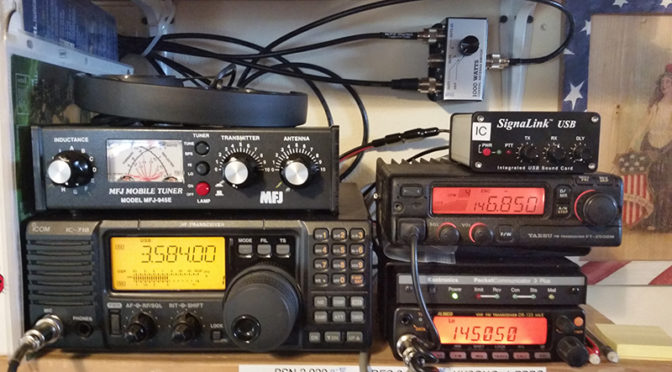
The packet station is an Alinco DR135 and a KPC3+ USB connected to a second Diamond X50A. I keep the station on 24/7 with the radio set at 5 watts. Overall it has very low power consumption.  I have no trouble reaching the digipeaters and I have a regular visitor from Shasta CA checking in on KK6GXG-1. I have also been able to get all the way down to the bay area via several other digipeaters. I have made a few VHF connections to the Winlink CMS system as well.

The VHF/UHF voice station is a Yaesu FT-2500M connected to a Diamond X50A. The two antennas are about the same height and separated by about 15 feet. For repeater communication, I usually have the power down to 5 watts. I will bump it up for simplex if I need to.

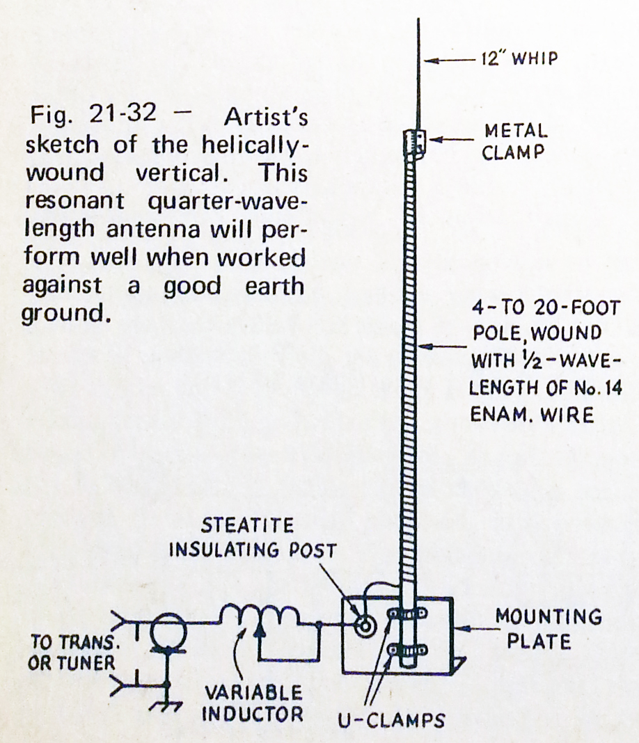
The HF station is an Icom IC-718. I have the Hy-Gain AV-18VS vertical which I have been using for 40-10 meters. It will tune up to 80 meters, but the 80 meter wire NVIS I built is more effective for 60-160 meters. I have both antennas switched into an MFJ-945E tuner and on to the radio. I have been making regular 75 meter contacts from Canada to California and east to Idaho, Colorado, Nevada, and Utah.

I have poked around on 40 and 20 meters but not much. I have been too busy with the NTS nets on 75 meters to go looking for anything else.

On the HF digital side, I have the 718 connected to a Signalink USB which works great for Winlink Winmor peer-to-peer and CMS connections as well as a wide variety of digital modes through fldigi.

I am looking for another HF radio to dedicate to digital modes, and I recently picked up a Kantronics KAM-XL which has VHF/UHF and HF ports that would allow me to set up access to my PBBS on HF as well as VHF and cross-band digipeating, but that’s for the future.

My next area of attention is to get an old KPC-3 connected to an inexpensive VHF/UHF radio I already have and install them in the truck for mobile packet access. I may be able to work out an APRS system while I’m at it.

Well, that’s it for now. I’ll try not to wait for 4 months to update next time.

Until then…

73,
~Jon KK6GXG

40 Meter Antenna

With the direct conversion receiver now working and tuned into the 40 meter band, it’s time to get to work on a better choice of antenna. The dipole would be great if it were in the proper environment, but this indoor, RF noisy environment is not conducive to picking up much.

Since tuning the receiver to the band I have been picking up both voice and cw transmissions but they are deep in the band noise. The other issue is portability. While the dipole can be pulled down and packed up for field use, it won’t work well in a mobile environment and would be a chore at home to pull down and put back up. So a whip makes the most sense for now. If the whip works at home I can wind up the dipole and keep it in the ready for field use.

Right now my focus is on getting the receiver, antenna, and any needed matching equipment in place. Once that is all together I can turn my attention to filters, amplifiers, and a transmitter.

Scan from the 1975 ARRL Handbook, page 606.

The antenna is a helically wound vertical that I mentioned in a previous post All Aboard the Project Train. I ordered a six foot fiberglass safety flag whip for the core and a fresh 1.5 pound spool of 14 AWG copper magnet wire to get the project going.

Yesterday I started the antenna construction by unrolling the 66.5 feet of copper wire and marking it every five feet, mostly so I didn’t lose my count. After dinner I started winding the coil onto the fiberglass in a tight coil. The picture in the header for this post is the fiberglass with about 30 feet wound on.

20150422_093128
66.5′ of 14 AWG copper wound onto a6′ x 3/8″ fiberglass rod

After winding the rest of the wire onto the fiberglass I threaded a dentists tool in between the wire wraps up the full length of the rod to create the uniform spacing for the coil.

On reflection at this point I think I might have opted for an 8 or 10 foot rod. For most applications it might be a better choice but neither would fit well indoors so 6 foot it is. I may build another antenna like this if it works well and try different lengths and diameters for different applications. A 10 foot whip would be better with a 1/2″ core and any longer would need 3/4″ or 1″ to remain stable unless it were placed inside a tube and filled with epoxy resin, another option. I haven’t tested any of these, I’m just spitballing with the structural integrity issue and weather resistance.

20150421_220832Now that the coil is done, the most difficult and time consuming part I think, it is time to move on to the spike and the base.

The plan for the spike is to pick up a small piece of 3/8″ copper tubing about 4″ long and use a coax crimping tool to mechanically center and attach a 1/4″ steel rod to about 2″ then sweat solder it together. After the spike is properly affixed, scoot the coil up a bit and solder the copper wire to the tube, add some epoxy inside the tube and scoot it back onto the fiberglass rod. This should give plenty of mechanical stability to both the spike and the rod as well as a good electrical contact. To help prevent galvanic corrosion I will coat the steel/copper interface with a few coats of lacquer.

The base is where I am going to have to think some more. The diagram calls for a variable inductor at the base of the antenna. I don’t think I will need this because I am planning on using an adapted Z-Match antenna tuning unit from chapter 23 of QRP Basics but that is for the next project.

OLYMPUS DIGITAL CAMERAIn the mean time I am thinking about using a PVC/ABS 90º conduit fitting with an access panel, cutting off and sealing up the right angle (on the bottom of the image), inserting the bottom of the antenna with the wire sticking up out of the box a little and filling the cavity with epoxy resin, leaving enough room to install an exterior lug fitting to attach the wire to on the inside.  For mechanical stability and to provide a secure mounting point I was thinking about using 6″ of conduit around the antenna and filling that with epoxy resin as well.

I hope to get the spike done this week and the base over the weekend. While out and about getting the final parts for the antenna I will be hitting HSC for the parts for the Z-Match. Another busy week for radio. 🙂

73,
~Jon KK6GXG

BreadboardRadio Kits

Breadboard Radio KitsOn Wednesday I received some awesome mail, the kits I ordered from BreadboardRadio.com arrived! As I am inclined to do, I opened things up and began organizing and inventorying the contents there in. Counter to the habits of a younger Jon, I printed all of the distructions, what I tend call them, and read them all, cover-to-cover. Even before setting up the first project!

I completed the electronics of the Matchstick antenna tuner Wednesday evening. Without a receiver or transmitter I couldn’t do much with it. Yesterday I finished the electronics of the Sawdust regenerative receiver and proceeded to spend over four hours tuning up and down the 40 meter band.

There was some broadcast, not sure if it was AM bleed or SW though I am leaning towards SW, phone (voice), and some digital transmissions. I believe I heard both RTTY (Teletype) and PSK31 (ASCII keyboard-to-keyboard). No CW though. I was really hoping for some Morse Code. Lots of band noise. The solar storm this week is making for some interesting sounds.

Progress shots were taken and will be uploaded to the usual places, here, G+, and Flickr, but I wanted to get them all wrapped up nice and purdy first. Because they are kits and will be done over the weekend most likely, I figured it was worth the wait. I am going to post about each kit separately though.

When I said a kit was completed, I deviated from the distructions in one respect. They called for finishing the wood bases before the electronics so the mounting of said electronics goes directly onto a clean, freshly finished mounting. Well, I didn’t do that.

Matchstick antenna tuner kit from BreadboardRadio.com

I wanted to finish all of the bases at the same time… and, okay, I wanted to get a radio on the air ASAP. So, yes I will finish the bases, but it will be all at once. I I am not sure with what finish I will be using so for now the kits get mounted on the raw base.

Before the kits arrived I built a simple ½  λ dipole to have something to test the radios with, and it does work, but I don’t like the feed point or the wire spools. I didn’t take any pictures because, well I’m not particularly proud of it. That may sound vane, and it is, but some hack jobs just shouldn’t have pictorial evidence.

To resolve the antenna issues and to address the bases for the the kits I think a little fabricating shop time is in order. This morning I am designing the feed point / spools and after day-job stuff I will look at finishing materials for the kits.

73,

~Jon KK6GXG