Tag Archives: homebrew

RTFM aka Read The Datasheet

A lot going on these days. Lets start with something educational… No, don’t run away… it’s not that bad.

RTFM or Read The Freaking Manual is directed in this case to datasheets for semiconductors. And this is where we begin our lesson for today.

20150527_113247
The VXO dismounted from the LO/Buffer for testing

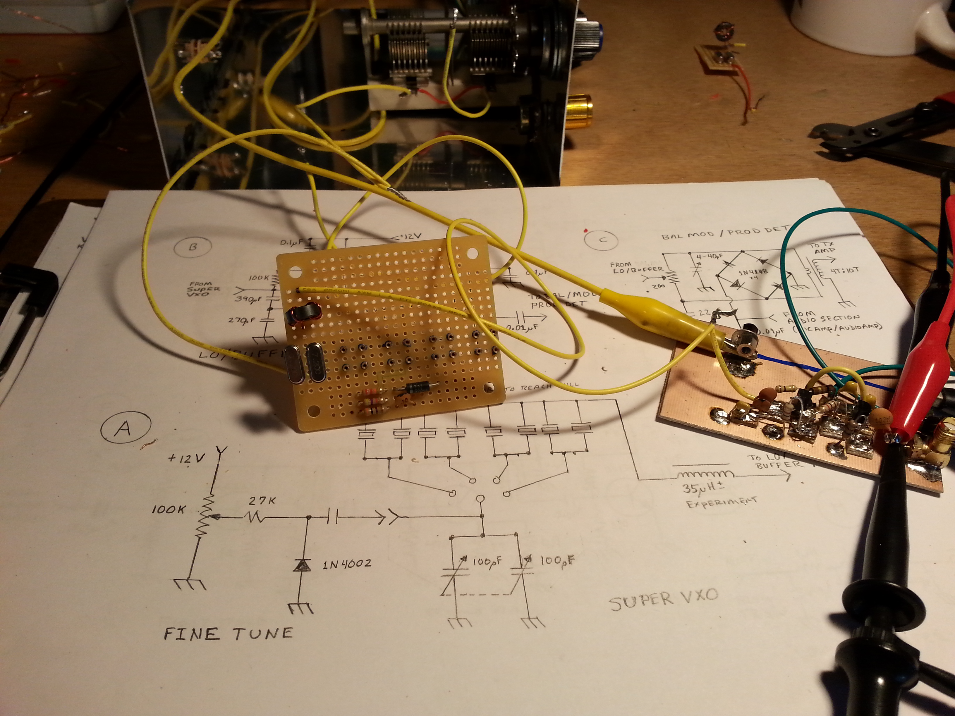
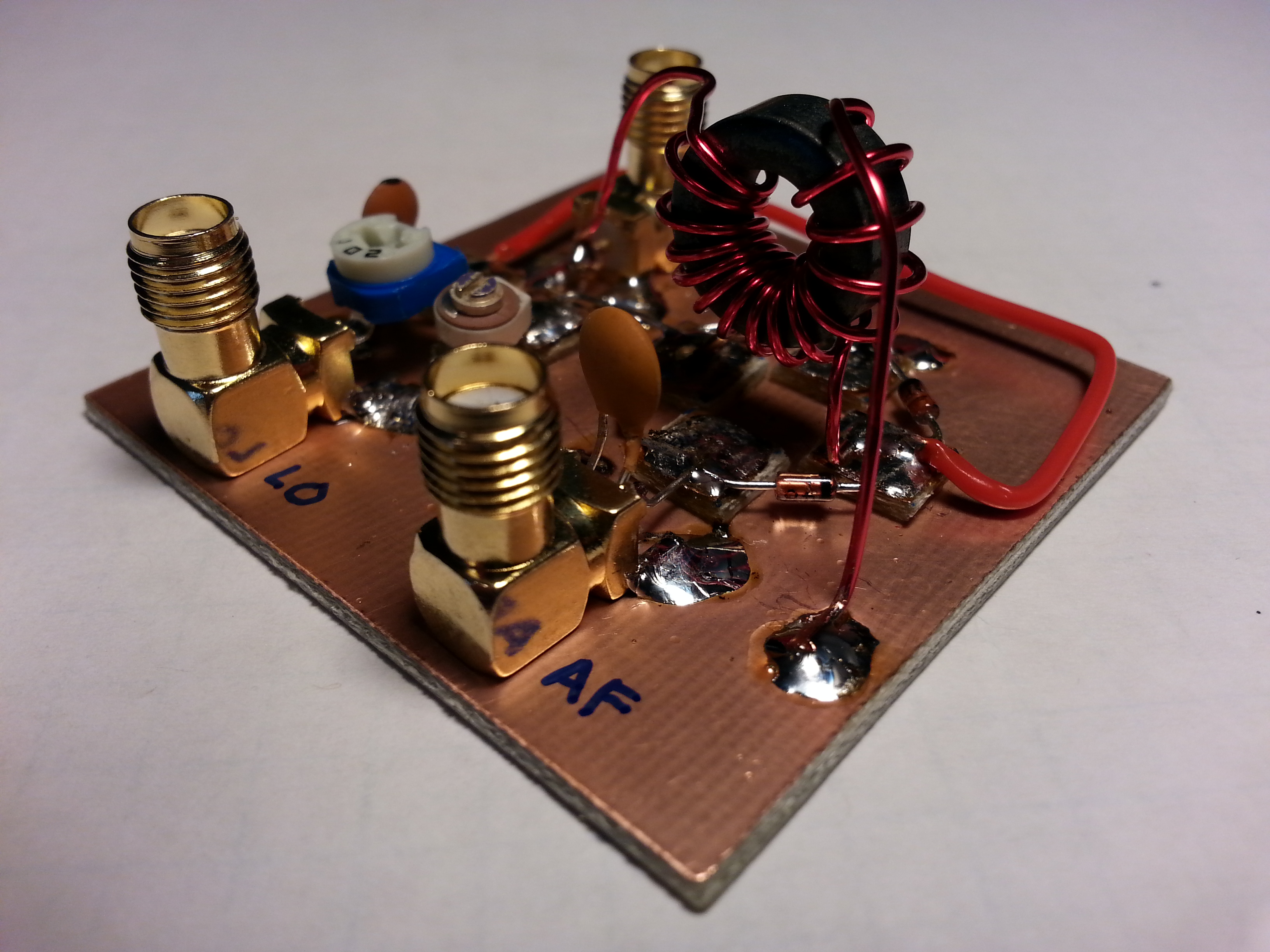
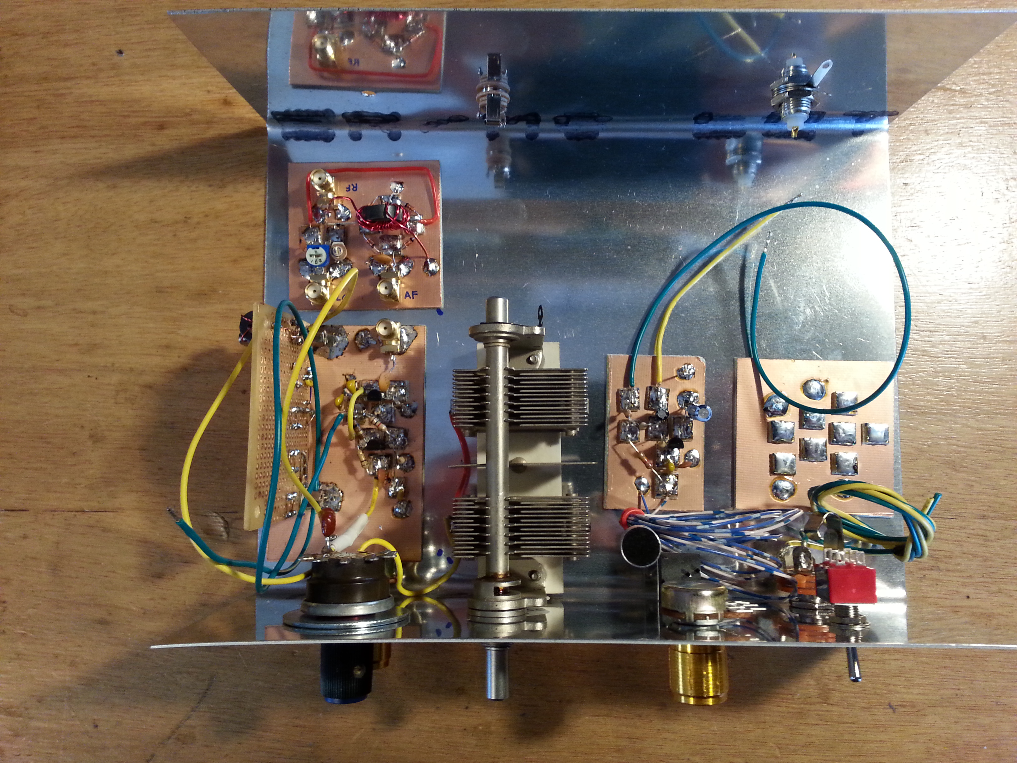
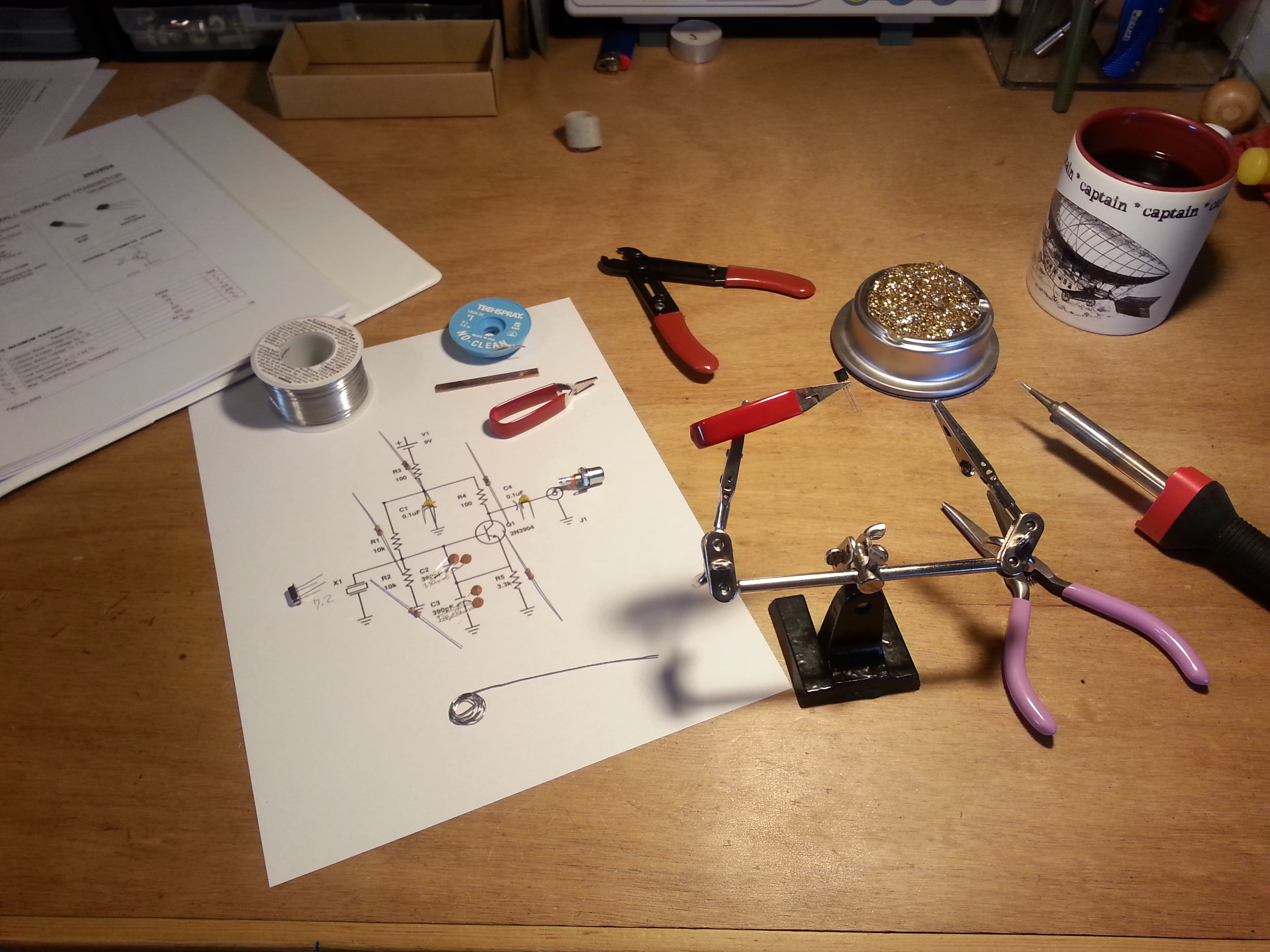
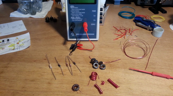
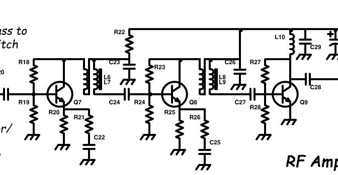
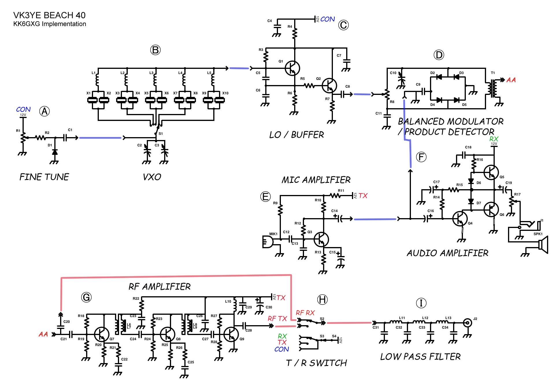
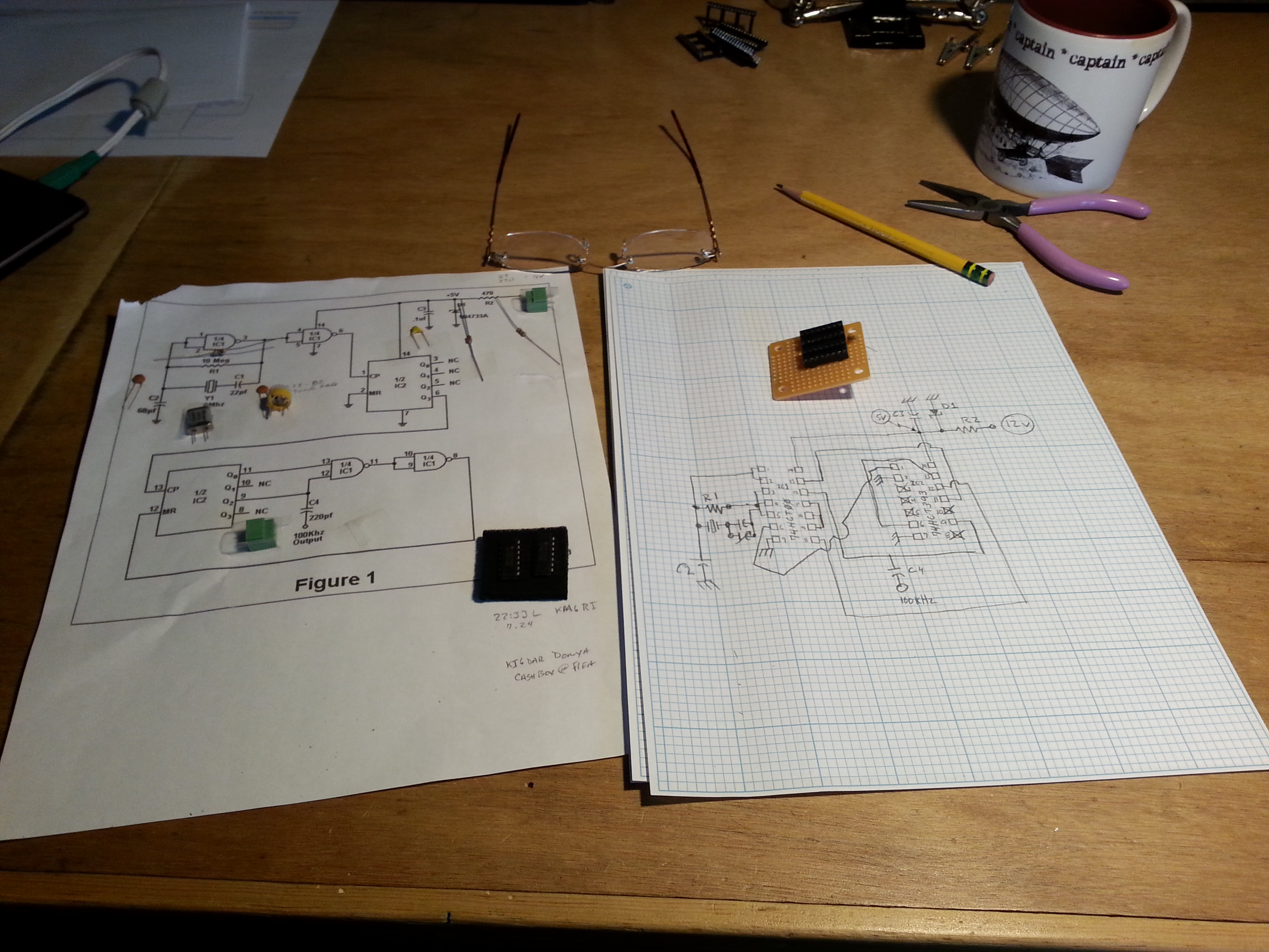
I have been working on the Beach 40 project for a few weeks now and have made some progress but I was having some difficulty with the VXO (variable crystal oscillator) and the LO/Buffer (local oscillator and buffer.) The oscillator section is supposed to generate an RF carrier frequency, in this case close to 7.2 MHz. I wasn’t generating the carrier and I couldn’t figure out why.

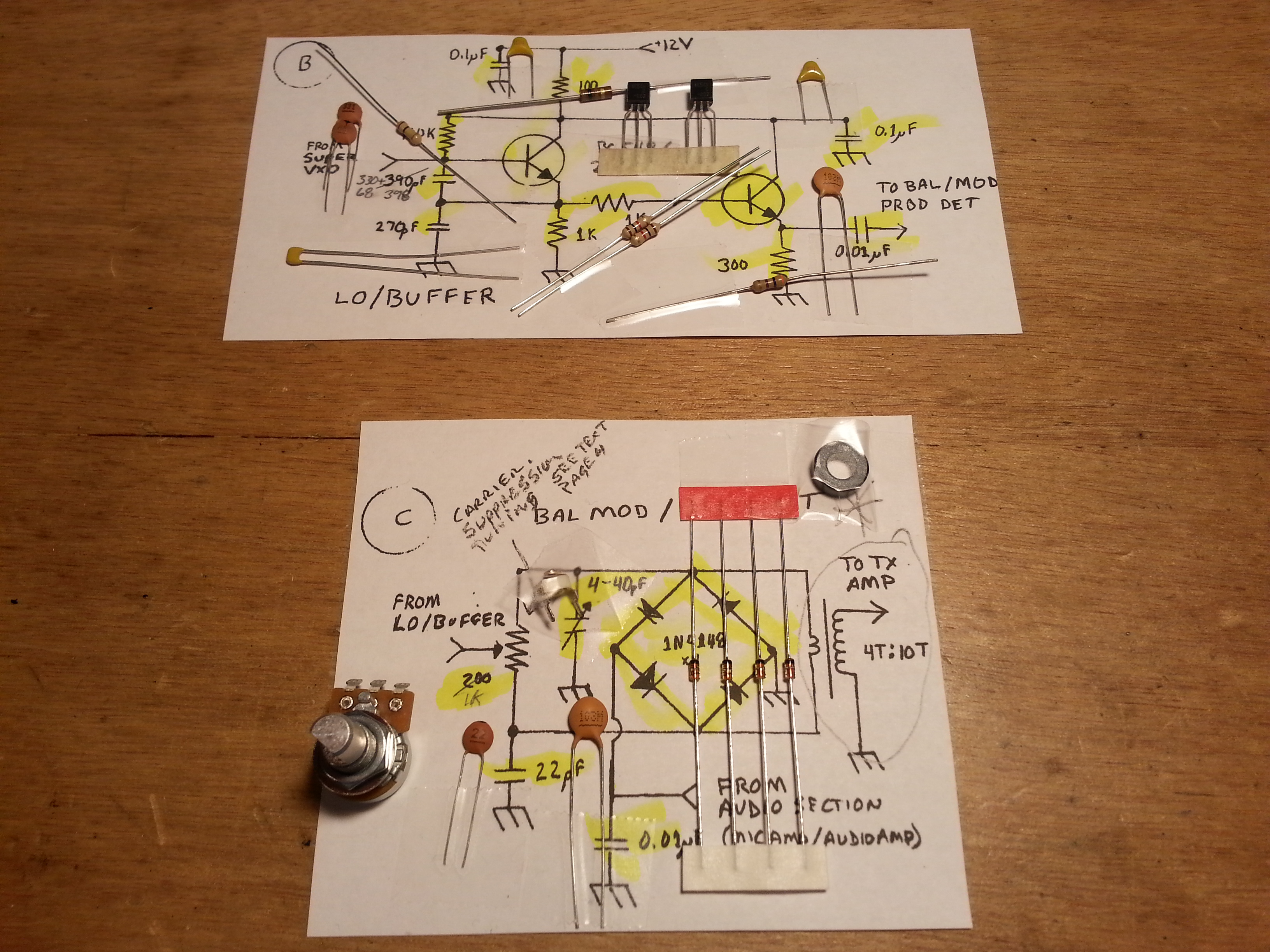
I decided to put these sections aside and move on to the next section and ruminate on the problem for a while. The next section in line was the Balanced Mixer / Product Detector but I was missing a component that I was still waiting to arrive, so on to the next stage, the Microphone Amplifier.

20150525_135559
The Mic Amp has the mic element temporarily direct wired for testing

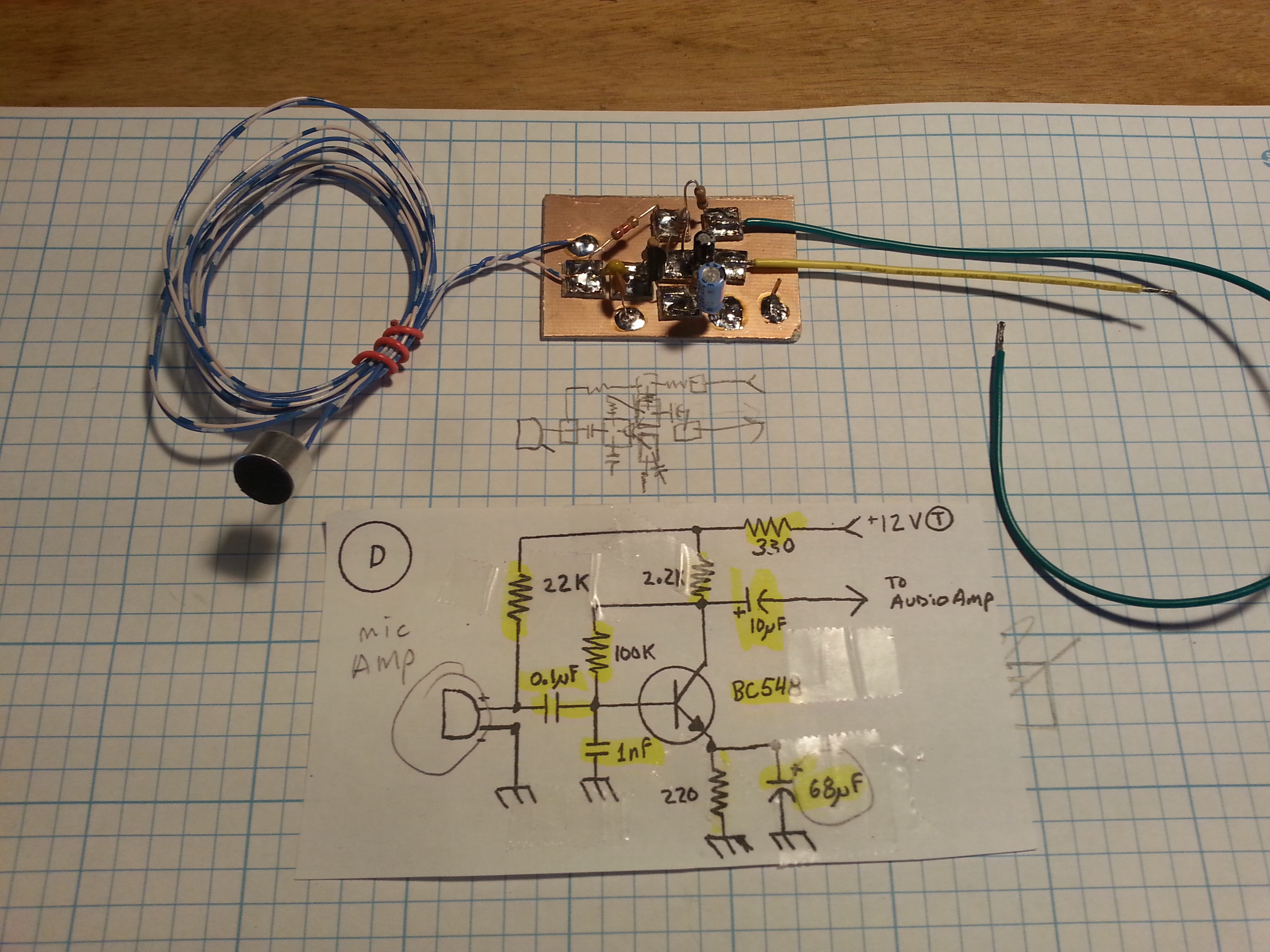
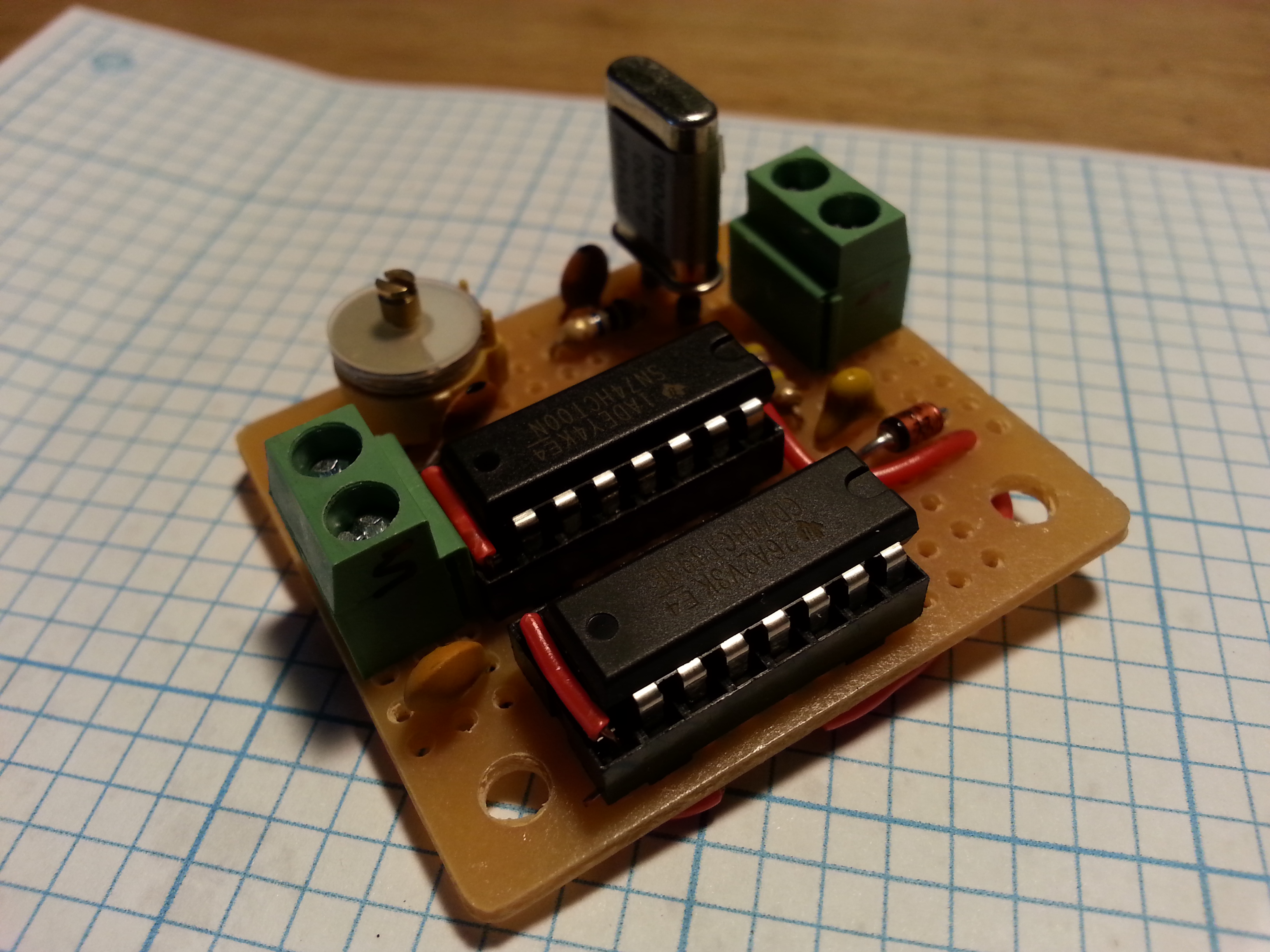
Laying out the parts physical locations on the circuit board I came to the transistor, one I hadn’t worked with before. So I decided to look up the data sheet and be sure of the pin-out. It wasn’t what I was expecting it to be, and then it hit me, like a Log from BLAMO! My oscillator wasn’t oscillating because I had the pinout wrong on the transistors! I finished the Mic Amp and the part arrived for the BM/PD.

20150527_154019
The Balanced Mixer/ Product Detector. Ain’t she a beaut!

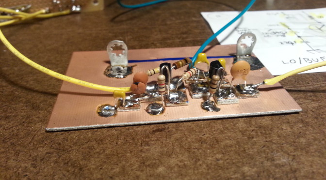
I moved on to the BM/PD and finished it then looked up the transistors on the LO/Buffer and sure enough, I had them in backwards.

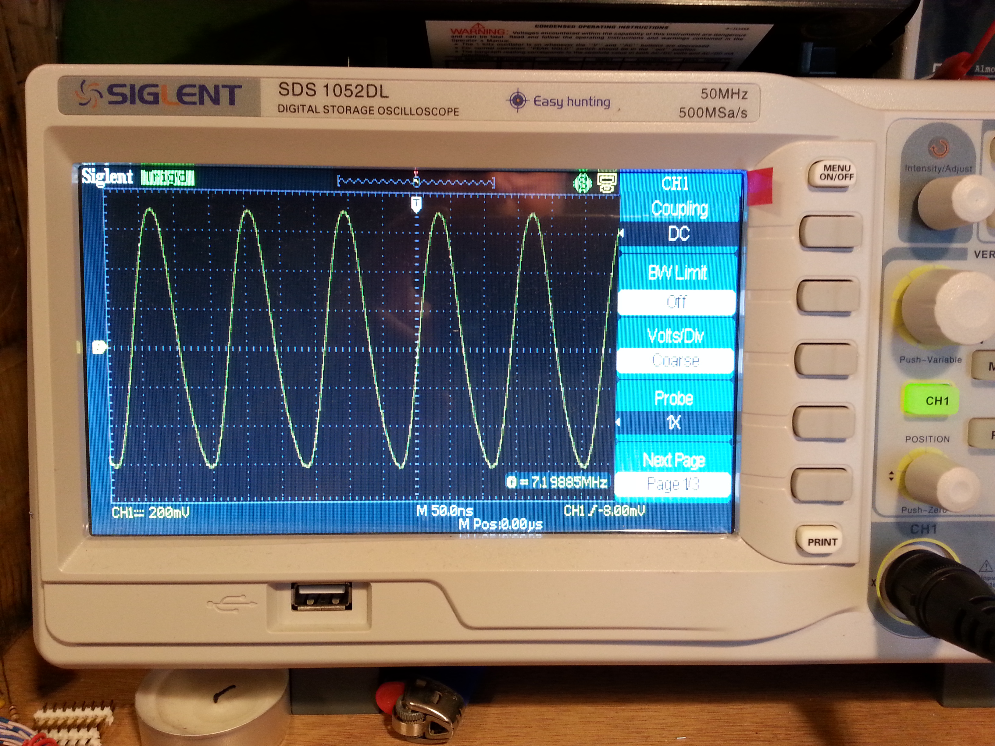
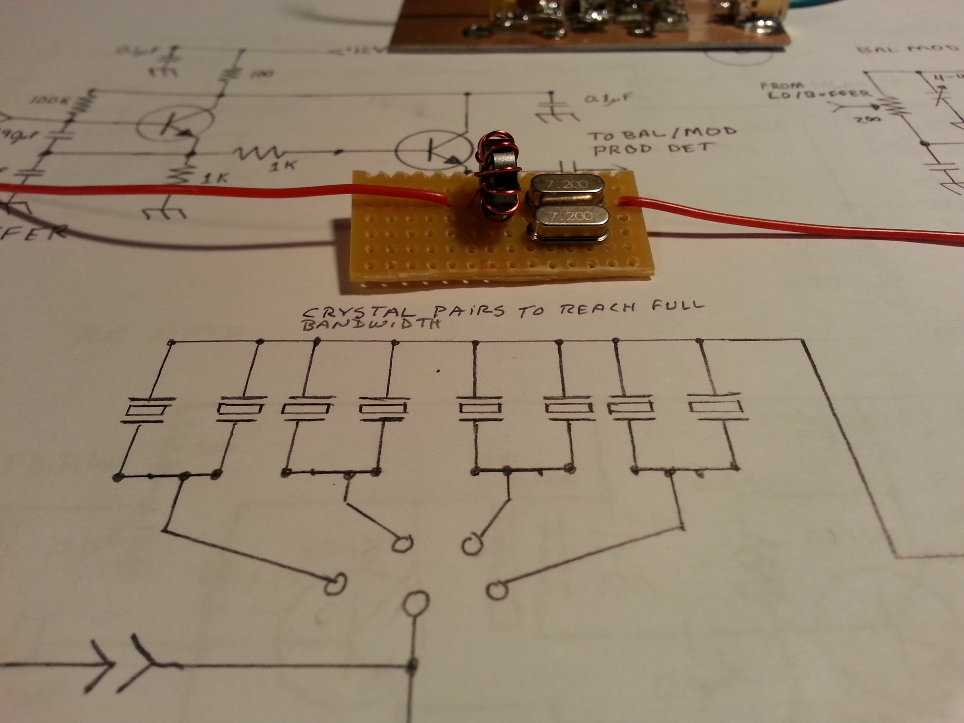
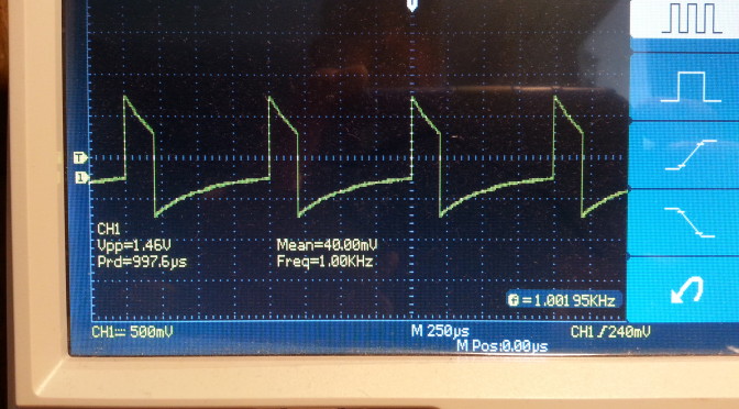
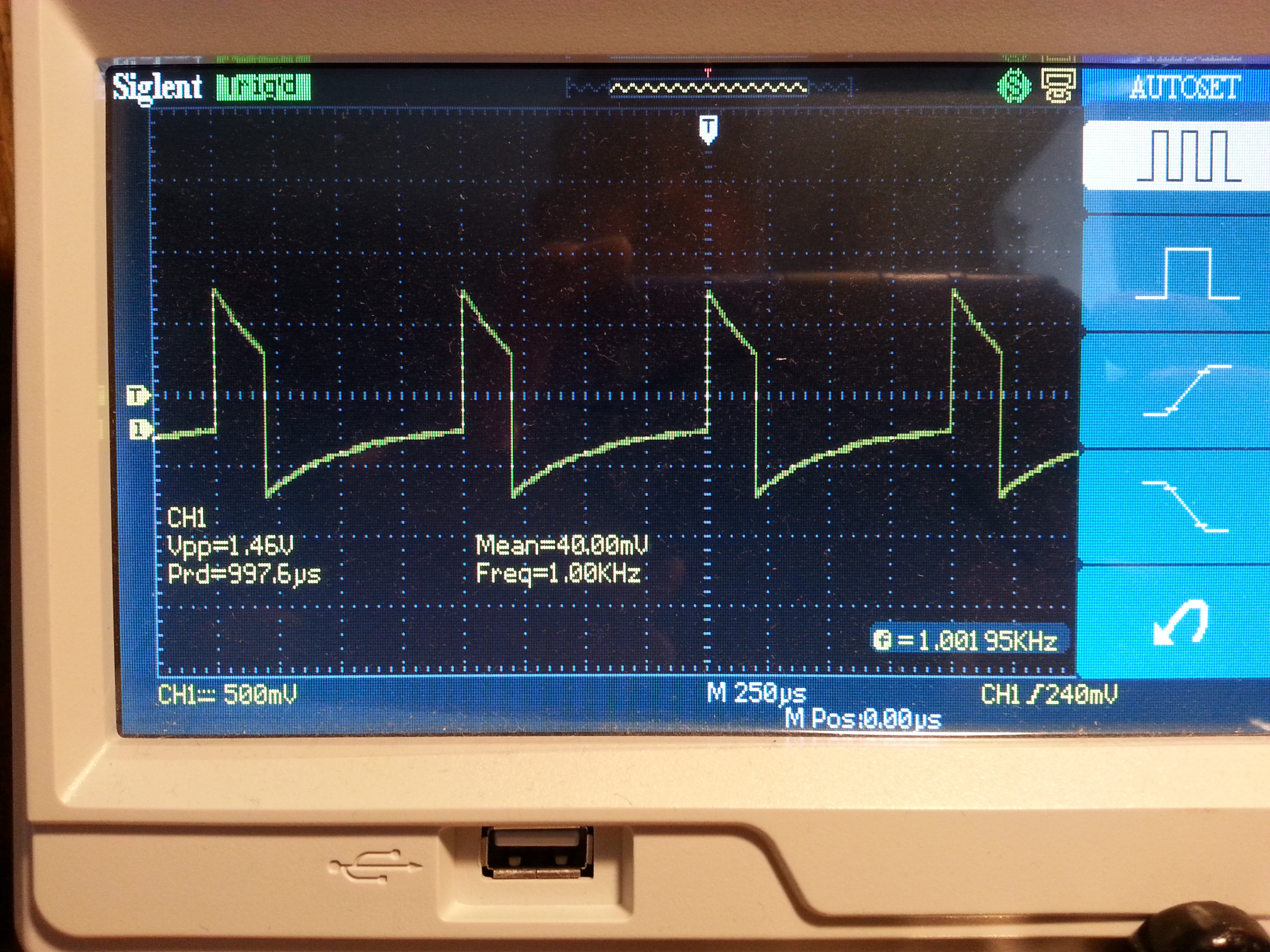
With a little coaxing and cajoling, and construction of a really scaled down crystal oscillator for testing, I got them turned around and everything back in place, well sort of. I missed a jumper and had to go back and solder that back down, but the after that the oscillator was oscillating like a good little oscillator should. Oscillation!

With a little tweaking and and the removal of the Fine Tuning circuit that I still haven’t figured out, I am back on track and only three sections shy of a full transceiver.  At present I have the sections built for a QRPpp transmitter a very, very, very, very low power transmitter, somewhere around the microwatt range but I should be able to modulate a voice transmission a foot or so to my DC receiver.

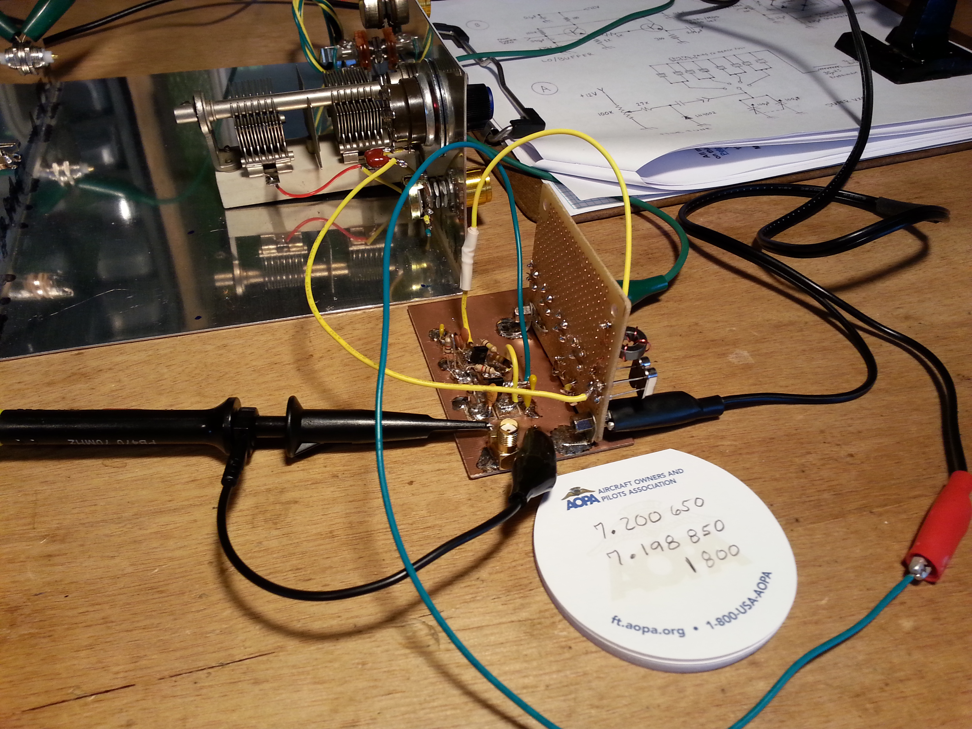
The Mic Amp test is actually a test of the VXO, LO/Buffer, Balanced Mixer, and Mic Amp sections and has me transmitting some AF (audio frequency) along with the carrier through the Balanced Mixer to help locate the signal in the band. Once I locate the signal on a separate receiver it’s time to tune out, or “suppress”, the carrier signal on the BM/PD section.  I’ll be doing just that in the next few days. Hopefully I will remember to video the test and post the video.

I already checked out the VXO and LO/Buffer when I checked the frequency. I can check the Mic Amp just by hooking it up to a speaker, which I will. Then the BM/PD gets it’s big on-air check out.

20150527_163139
CCW from top left: Balanced Mixer/Product Detector, Local Oscillator/Buffer with VXO mounted vertically, tuning capacitor, Mic Amp, and Audio Amp with just the tinned pads on the board

All that’s left to have a working receiver is building the Audio Amplifier which I have already laid out, I just need to solder the parts down and test. After that I need to build the RF Amp to have a transmitter. I will want to also complete the Low Pass Filter before transmitting though. I don’t want to splatter the band or anything.

So the schedule for now looks like a completed Beach 40 transceiver should be on the bench next weekend or there abouts.

That’s all for today.

73,
~Jon KK6GXG

Radio Kits

When I first started this blog I planned on posting a separate page for each project I did. After some thinking on the matter I decided that scratch-built projects would have a page dedicated to them.

20150518_213658
L/C Meter IIB from Almost All Digital Electronics AADE.com

The last post was an example of a project while important and interesting, I don’t think it rated a page. I am of course referring to the post on the AADE L/C Meter IIB.  Part of the reason I’m not devoting a page to the project is that it is a kit, a great kit, but still a kit.

Don’t get me wrong on this, kits can be a really useful tool. Often times kits can cost less that the parts purchased individually. They can also be useful in overcoming sourcing issues.

20150403_090944
Scratch-built, from paper to product

For the beginning builder kits are a great way to get your feet wet and try the building process as well as exercising the construction skills needed in scratch-building. A kit can get you on-the-air faster than scratch-built as well. Kits give a potential scratch-builder a chance to see if they actually like building.

Kits also offer a choice for the builder. The kit can be built by just filling up the board following the instructions, or if you are looking at going scratch-built later on, taking the time to trace things out and compare the schematic with the board layout, and understanding what components perform what function along with how and why things are placed as they are goes a long way in improving your understanding of the circuit.

While kits can be a good learning tool or refresher for the builder, they off-load a lot of the mental gymnastics involved in design, sourcing, layout, placement, and proximity matters. Or at least they should, a poorly designed kit can be a real challenge for even the most skilled builders.

I decided to post about kits rather than page them because of this off-loading. While the kit may be of educational value, it is the mental exercise not the physical work that provides the real educational benefit. I don’t think I would be bringing much to the table beyond the instructions that come with the kit.

Breadboard Radio Kits
4 kits from BreadboardRadio.com waiting to be assembled

So don’t be surprised when you see a project as a post rather than a page. I will start the trend in my next post when I show off the BreadboardRadio.com kits I built before beginning my 40 meter Direct Conversion receiver. I will likely set up a Kits page as an index to kit projects if it looks like I need one.

Stay tuned and 73,
~Jon KK6GXG

The AADE L/C Meter IIB

If you don’t work with RF electronics the need for an L/C meter may not be readily apparent. If you work with RF, you have likely found capacitors and inductors in the junk pile and played hobb trying to figure out the value, unless of course they were marked.

My first homebrew toroid inductor. Aint she purdy?

If you wind your own inductors or make your own capacitors the need for an L/C meter is a no-brainer. I bought a cheap Chinese manufactured meter and it was no bueno. No redeeming qualities what-so-ever.

Within the Amateure Radio world AADE (Almost All Digital Electronics)  and the L/C Meter IIB has earned an almost legendary reputation for being just the piece of equipment the homebrew ameture needs.

20150518_173544Being a homebrew ameture and a recycler of electronic components, I decided to buy the L/C Meter IIB kit and build it. The kit itself is very straight forward. Assembly is well documented and easy to follow.

I have been generating a lot of solder smoke lately so I may have an advantage here in assembly speed but I went from shipping box to functioning test equipment in about 4 hours.

20150518_194352Starting with full parts inventory I went right into construction. The parts list is only one sheet and it is very detailed. After checking in all of the parts and tagging them to the parts sheet I fired up the soldering iron  and started melting metal. Filling the printed circuit board didn’t take long at all.

Th20150518_212344
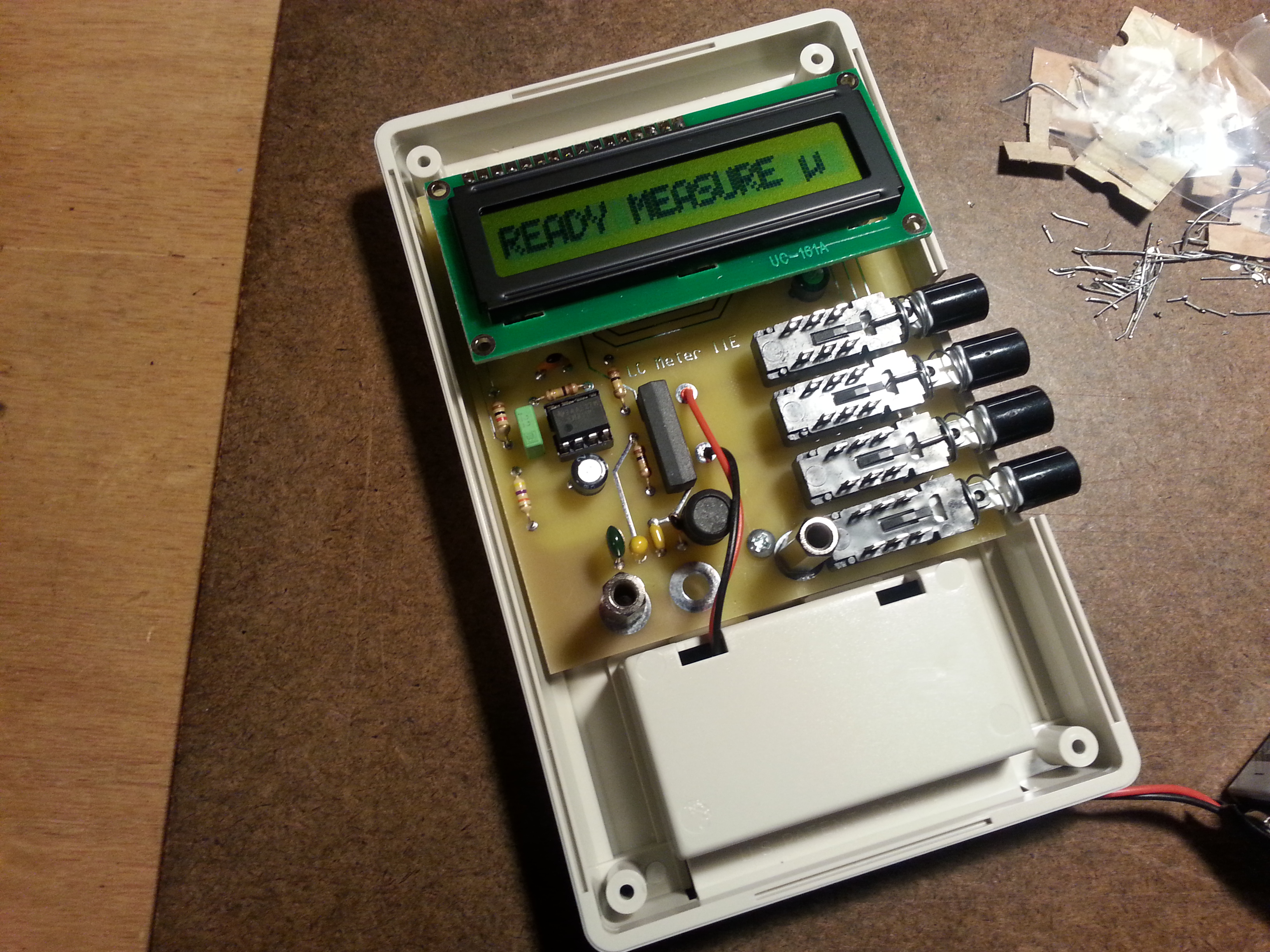
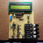
e only hiccough was technician error. I got all of the components soldered in, mounted the board in the back of the case, mounted the LCD, and plugged in the battery. When I turned on the power switch I got nothing. I knew from reading the instructions fancy that that a common oversight is that the contrast pot should be turned fully clockwise. When I went to check the pot I noticed something missing, I forgot to install the IC’s in the sockets. Doh!

20150518_215451
A great product that supports a US, family owned and operated business AADE L/C Meter IIB

After installing the IC’s I checked the pot and Voilà! A working L/C meter.

At $100 a kit that looks as simple as this one does you may be tempted to buy a cheaper factory assembled meter. I would strongly advise against it. A comparable factory manufactured meter will set you back at least twice what the L/C Meter IIB will, probably more.

LC meter
Save yourself the time, trouble, and expense of having to return this piece of junk, don’t buy it in the first place

I purchased a cheap meter for $38, paid $6 for shipping and another $8 to return it. Sure, it looks nice but it is complete garbage.

And if you need something else to push you over the fence on this purchasing decision, buying from AADE supports a family run US business that takes pride in the work they do. Now that’s a bargain at any price.

Solder smoke is filling the air as I continue work on the 40 meter Beach 40 DSB transceiver so check the build page for updates. I will be making an update tomorrow!

73 for now,
~Jon KK6GXG

Work On The Beach 40 Begins

Back to building! I finalized the drawings for my implementation of VK3YE’s Beach 40 DSB Transceiver. I created a project page for it here.  I also finished the the “final” version of the diagram, at least until I get the physical build under way. I will be updating the diagram on the project page but not here so if you are interested in this project, check out the build page.

VK3YE-Beach-40-KK6GXG
Here is the full diagram I completed today. Click for full size image

While I am heating up the soldering iron tonight, another important part of this project is the documentation. Not only am I going to be updating the project page as the build progresses I will also be keeping a lab journal.

This is something new for me. I have never been skilled at keeping lab notes. This is something I need to work on now that I am getting more involved in RF electronics as an experimenter.

That’s it for now. More to come.

73,
~Jon KK6GXG

Marker Generator and more

20150507_190019Picking up where I left off in the last post, I got the drill bits and finished the 40 meter Helically Wound Vertical antenna. I will get a project page up soon.

Now when I say “finished”, what I mean is the antenna is useable. I still need to seal and cover it but I wanted to get it all tuned up first. As far a receiving goes, the vertical is out performing the dipole strung in the house just sitting on the floor leaning up against the wall next the operating station, so it’s looking good.

I need to finish the tuning with a transmitter on it. Since the only transmitter I have for 40 meters is a CW 250mW transmitter I am holding off on that.

20150508_121409In the mean time I put together a Marker Signal Generator. The design takes an 8 MHz crystal and divides the signal down several time ending up with the desired 1 kHz signal with many harmonics to mark out a tuning dial in 1 kHz increments.

20150508_150243It was fun to build and I leaned a little about some ICs I had never used and some of the basics of working with multiple devices in a single package.

When I came to function, I was very disappointed. The oscillator was anything but stable and we very dependant on an extremely stable input voltage. The onboard diode voltage regulations stunk so I tuned down the power supply from 12 volts to the 5 the ICs need.

20150508_153648At this point I was finally able to calm down the oscillator and get close to 1 kHz I was hoping for. A millivolt up or down and the frequency was out. Not a particularly useable device as it sits but it does give me some ideas for using out of band crystals to generate a signal.

As always, this is the whole point, to experiment and learn about RF design by doing, not just reading and modeling on a computer.

The big news, and the reason I missed a post last week is that I have been doing some research on finding my next big build project. The winning design was the Beach 40 by VK3YE. I have been scouring the web looking for a simple phone (voice) transmitter. I was hoping for SSB (Single SideBand) but the Beach 40 DSB (Double SideBand Suppressed Carrier) is simple and straightforward as is.

IMG_20150513_125237Being me, I had to make some modifications to the design and tweak a few things. One of the great things about this design s that it uses discrete components rather than ICs.

At one point Peter (VK3YE) recommends changing the audio amplifier to one that uses the LM386 chip rather than discrete components because the output is rather low. Since one of the main reasons I chose this project was to keep to available discrete components I went out in search of a different audio amp.

Enter Arv Evans K7HKL and his Discrete Component AF Amplifier paper. By the way, at least via email, Arv is a really nice guy. Thanks for the help Arv!

20150513_170104Now with the circuits mostly settled and parts enroute, Digi-Key arrived a day early! 🙂 I sat down tonight and began kitting the parts for each of the transceiver subsections beginning with the Super VXO. I am only installing one crystal set right now but the plan is to set it up for several banks of crystals. I also had some ideas as to using the banks for multiple bands as well as sections of a single band, but that’s for later.

20150513_202942I also kitted the Local Oscillator/Buffer and the Balanced Modulator/Product Detector sections. There are a few bits that will need some refinement, mostly inductors, but these will be addressed as needed.

And speaking of inductors, since I sent back that crappy one I am still in need of one. I will be ordering one tomorrow because I wont get far in this build without one. The goal is to have this radio up and running before Field Day June 27-28.

Look for a project page soon.

Till next time, 73,
~Jon KK6GXG

LC Meter Disappointment

LC meter
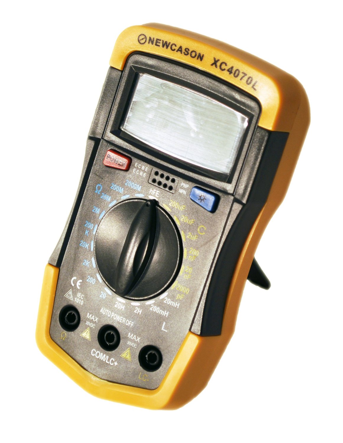
The Newcason XC4070L Handheld LCR Meter I ordered showed up on Monday. Wow, what a disappointment. No stability in measurements whatsoever and I’m not talking bounce between two consecutive numbers. 32 ρF to 64 ρF on a 50 ρF capacitor which by the way I checked with another meter that pegged it at 49 ρF.  This puppy is on the express return train.

20150505_085212I did get something good done while testing the meter. I wanted to make a set of alligator clips on banana plugs to easily check through-the-board components. I wanted to make a set of these for some time. Now I have them.

20150505_085407One of the advantages of using these is that it reduces the inductance and capacitance errors that can be introduced by some meter cables and close proximity of hands.

In other pending order news, I have the tap and dies for the antenna. Of course I am waiting on the drills. So there the tap and dies sit, on the group W bench, just waiting on the  for the drills.

20150501_131901As soon as I get the drills I should be able to get all of the antenna parts all connected up so I can start tuning and testing. Then I can move on to the ATU.

Thats it for now, 73,
~Jon KK6GXG

Package Pending

shopping-cart-blur-hi
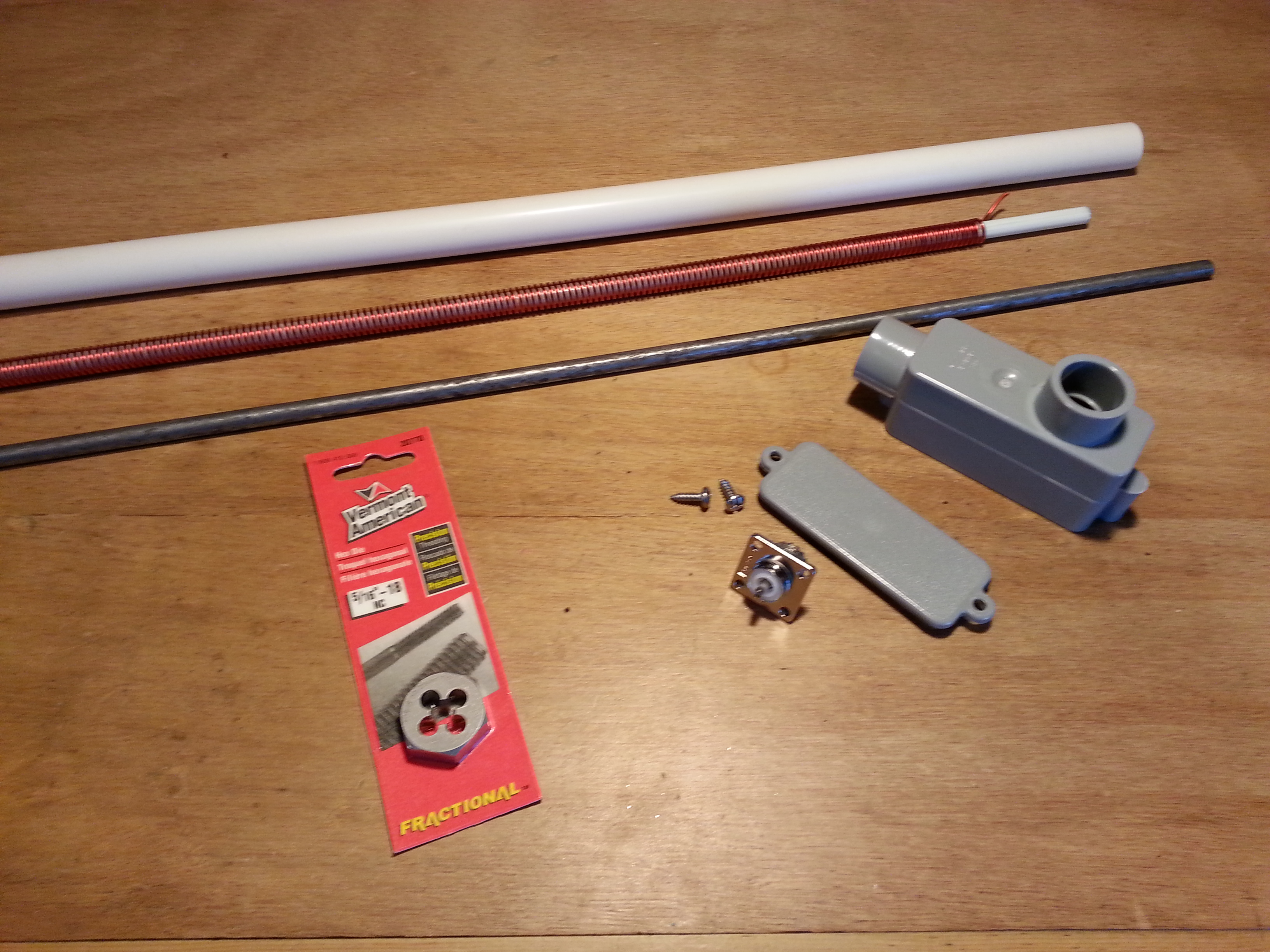
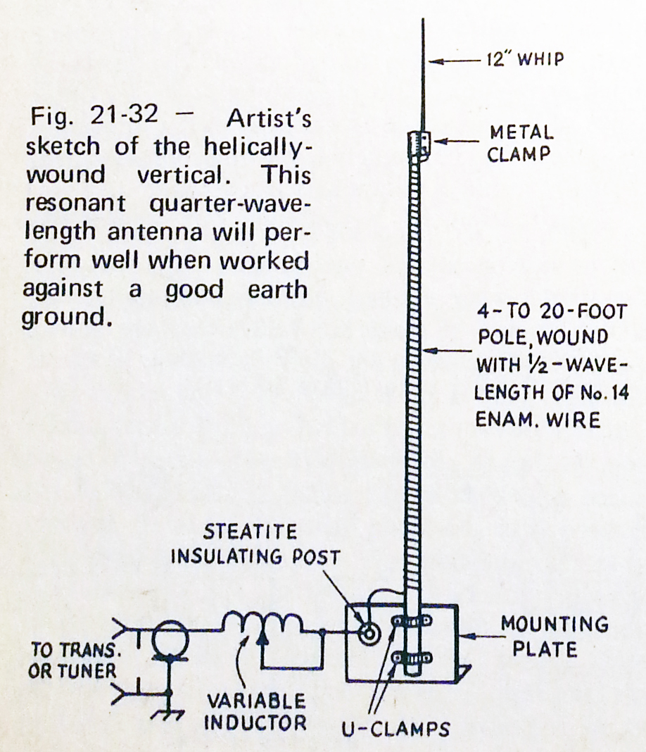
I have some tap and dies on order that I need to finish the 40 meter vertical antenna. I also have some parts  in transit that I need to get started on the antenna tuner which is the next project on deck. As well as the project parts I ordered a couple of items for stock.

One acquisition I have been needing is an LC meter to test inductors and capacitors.The one I ordered measures inductance (L), capacitance (C), resistance (R), and it also checks transistors. A very handy piece of equipment. I have several meters, digital and analog, nearly all measure resistance and voltage, a couple can check transistors, and one can test capacitance in a very limited range.

Since I am planning on making my own air dielectric capacitors, and a variety of inductors and transformers, having a wide scale LC meter will make this work much easier. It will also be a lot of help at flea markets and garage sales to check out components that I am interested in.

With all of this in transit I have some time to get some administrative stuff done. The main thing is to plan out the next few projects. The basic 40 meter direct conversion receiver is done, the antenna is almost done, and the antenna tuner is next with most of the parts enroute, so it makes sense to build a transmitter for 40 meters, I am leaning towards a CW/SSB transmitter.

One of the reasons I want to build CW/SSB is that it will add several other digital modes as well. Many of the digies can be connected straight throught the audio in/out ports on a computer or a handheld device. Leaving only the need to provide a key  or key signal to switch between the receiver and transmitter which could be done manualy or by serial connection to a RT swiching circuit in the radio.

It sounds a lot more complicated that it really is. With a little planning and some experimentation setting up a cable with a couple of connecters on each end will do the job nicely.

I will need to add a couple of circuits to the receiver at some point in the near future as well. An second stage audio amplifier is a must, and a switchable audio filters with bandwidths for CW, SSB, and something in the middle for digi, between first and second stage audio amplification. Neither of these should be all that dificult.

Once I get the 40 meter station all put together I will start work on building another station in another band. By this time I will have figured out a lot of the kinks and bugs and beable to build the second station much more efficiently.

At this point I’m not sure what the next band will be. There are 16 amateur bands currently with the potential of two more that I can gain access to under an experimental license so it is wide open. Each band presents new challenges, ether in technique or materials.

VHF and UHF present strictor tolerances and microwave (UHF-SHF) presents even more challenges. Most bands in HF will be about the same requirements as 40 meter since it is about the miiddle of the HF band. MF presents some challenges in radiators (antennas) because the wavelength is so long. LF presents more challenges in power and radiaors, not to mention the need for that experimental licence.

Fortunatly ist’s all about the fun and learning. As long as I am learning new things, honing skills, and having fun it’s all good.

Until next time, 73
~Jon KK6GXG

More 40 Meter Antenna Fun

20150430_155550Ya know that little voice, sounds like Han Solo in the back of your head “I got a bad feeling…” Yah, that one. Listen to it.

If you look at the image of the antenna base you may notice no screws holding the OS-239 in the bottom of the conduit angle. Now I didn’t leave it all up to gravity. I wound cotton twine around the threads a bunch to keep the connector centered in the hole and was hoping that because the epoxy was pretty thick it would hold down the connector.

20150430_163553Not exactly what I had hopped for. The string did act as a great fiber reinforcement to the epoxy though. Took me the better part of an hour to dig it all out and clear the threads this morning. I know things had gone wrong last night when I did the pour. Thats when I took this picture.

20150430_163541I figured trying to get the epoxy out of the conduit, off all of the components and try again would consume more time than just cleaning the mostly set up epoxy in the morning. Not to mention use up twice as much of a valuable resource. I was right on that one.

I had hoped to use a polyester resin but the can I had was older than I thought so I ended up using some West Systems T-88 structural epoxy, which was also a bit on the stale side so it was very thick. I had hoped that the thickness would be my saving grace on the SO-239. I had also hoped that a lot of the epoxy would filter down the PVC pipe with the antenna but not much of that happened either.

20150501_131622All in all things didn’t work out so bad. After some scaping, thread chasing, cutting and sanding a little gouging as well unfortunatly I managed to come out with a servicable antenna base and connector that is permanently sealed.

20150501_131150I double checked the connector with some feed cabling and all is well with that too. It won’t win any beauty contests and I’m okay with that. As long as it functions well and gives me a good match, that’s all that counts. I won’t be able to test it out until I get the last bits of the antenna finished.

If you look at the image at the top of the post you will see the steel whip is the same diameter as the fiberglass rod. I found some eighth inch bar stock in my materials along with a smaller brass rod so I shifted the plan slightly. I thought the whip should be of a diameter closer to the copper magnet wire of the antenna so the change made sense.

20150501_131901With the last few pieces cut all I need to do is drill, tap, and thread the antenna together then attach the wire to the spike and I can start finding resonance.

I should have the tap and die in the next few days so I should have a working, if not finished, antenna by the end of next week. This project seems to be taking a really long time to complete, and in a way it is. But I decided not to rush things along wouldn’t know it from the goo leak. I also have been doing a lot of day job stuff along the way so time has been divided.

That’s all for now, 73,
~Jon KK6GXG

40 Meter Antenna: Thought Process

I picked up some hardware to connect the antenna bits together into one cohesive unit. Sometimes with hardware you have to just go to the store and look around for solutions to a specific problem or situation.

20150426_122414
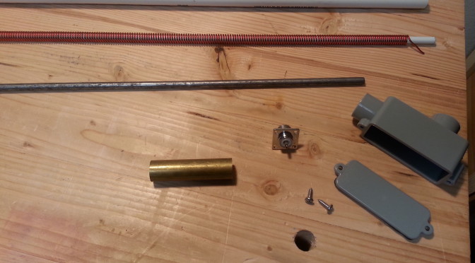
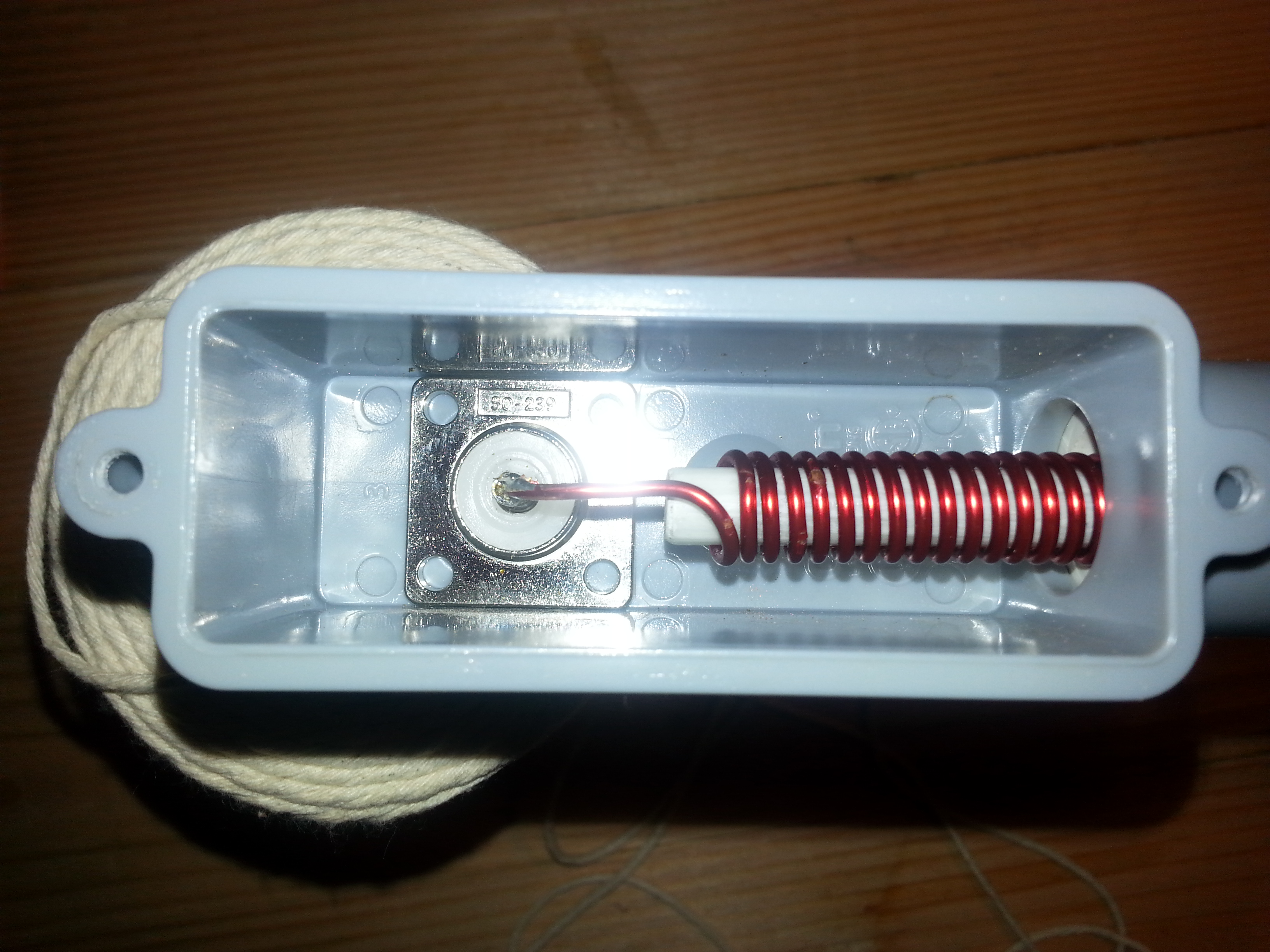
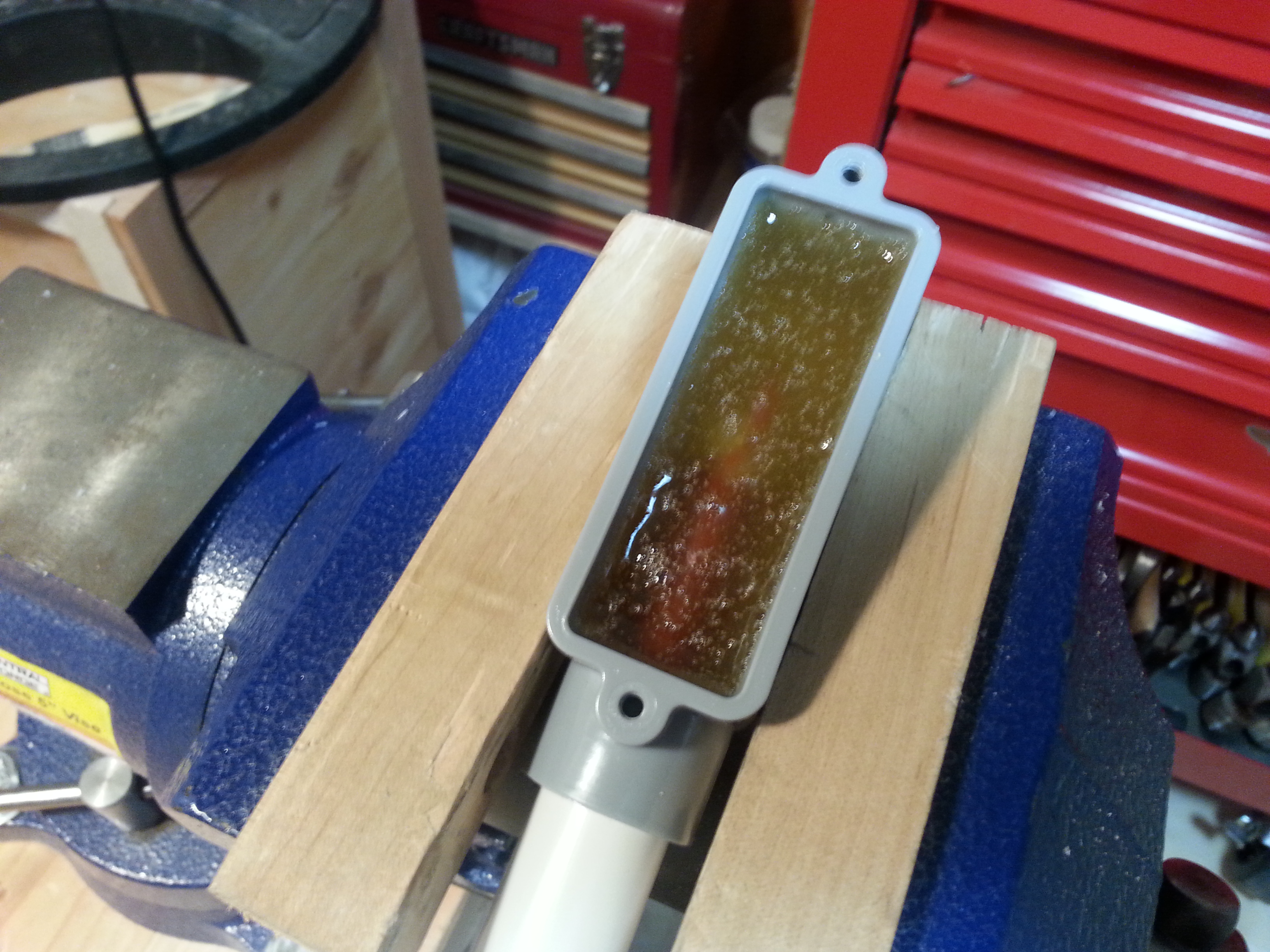
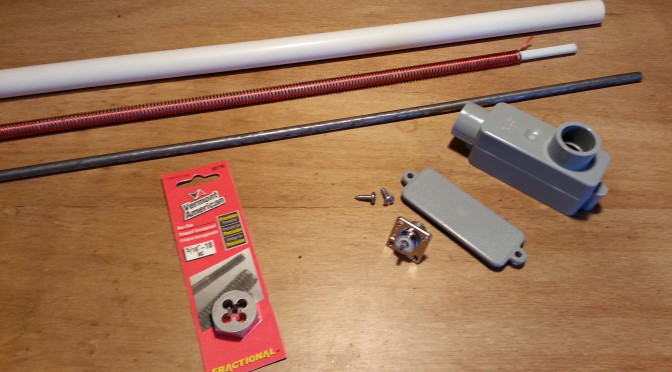
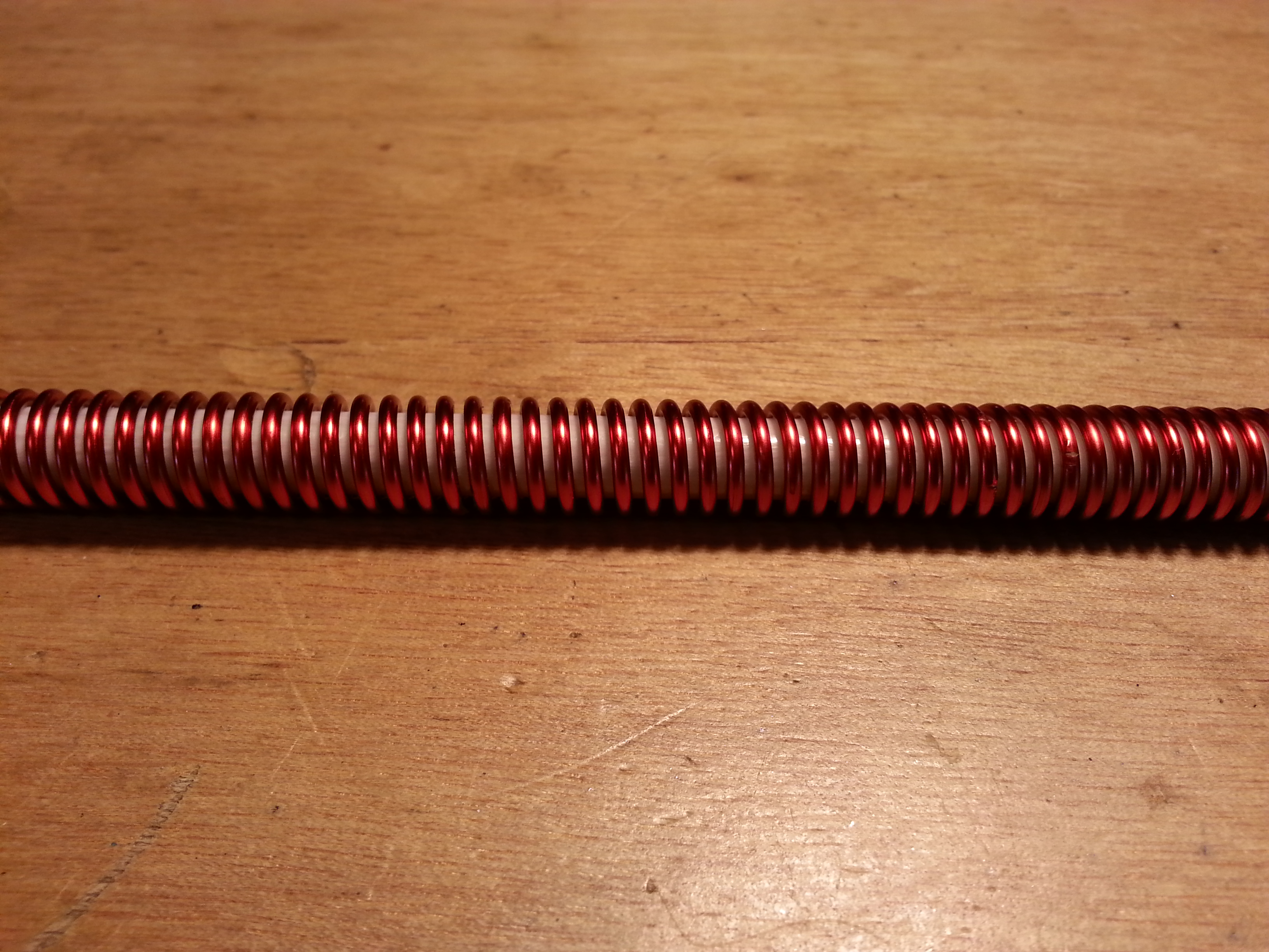
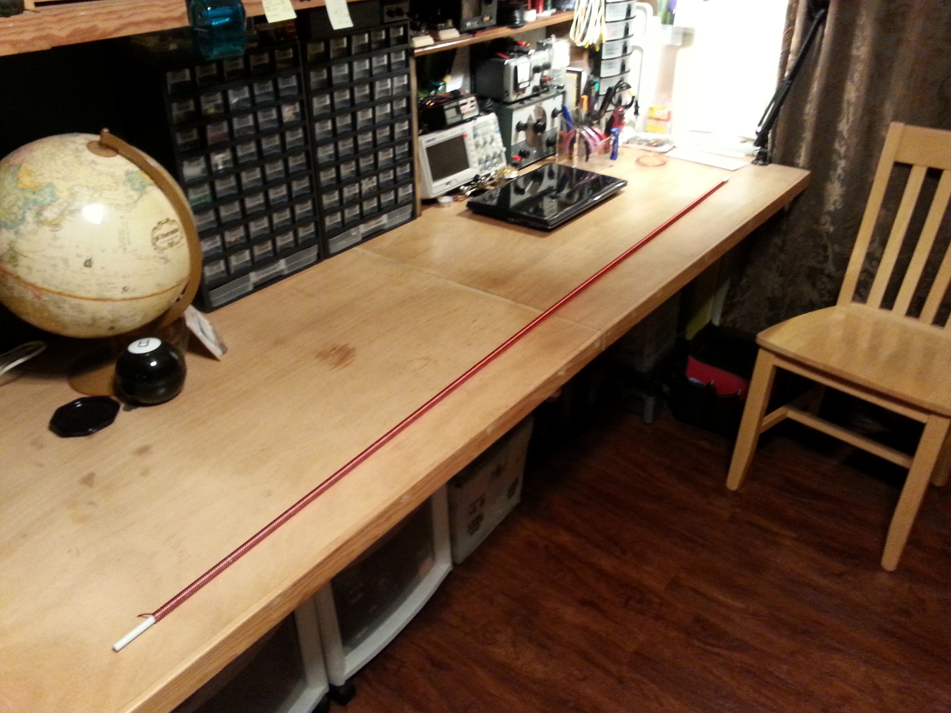
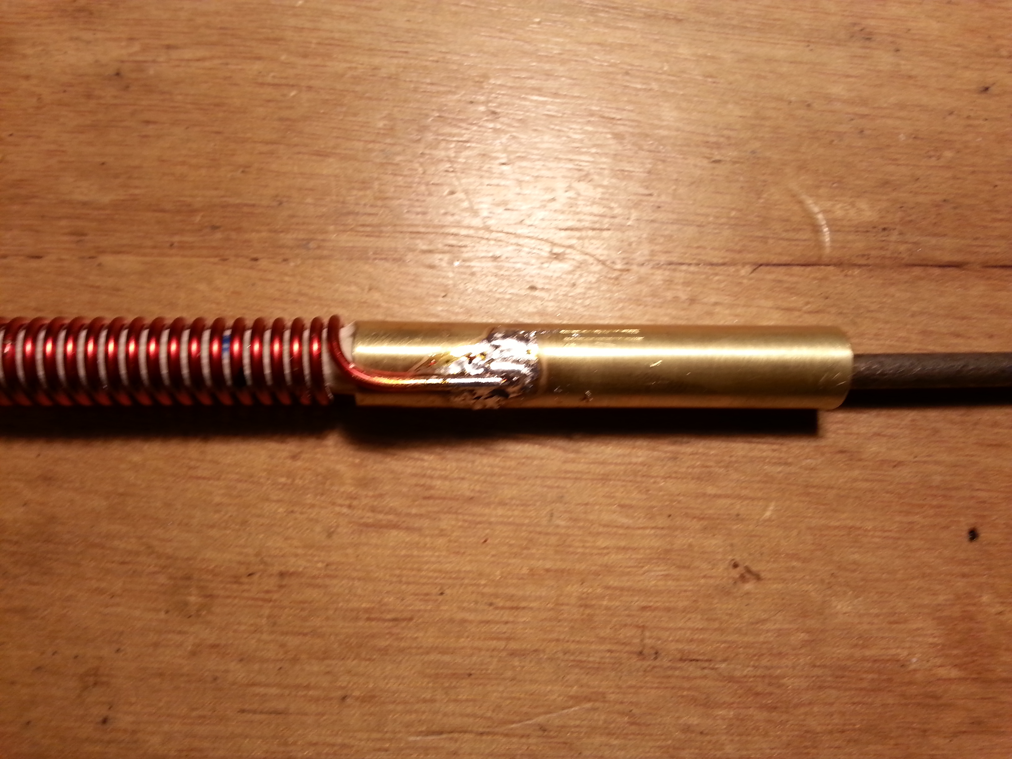
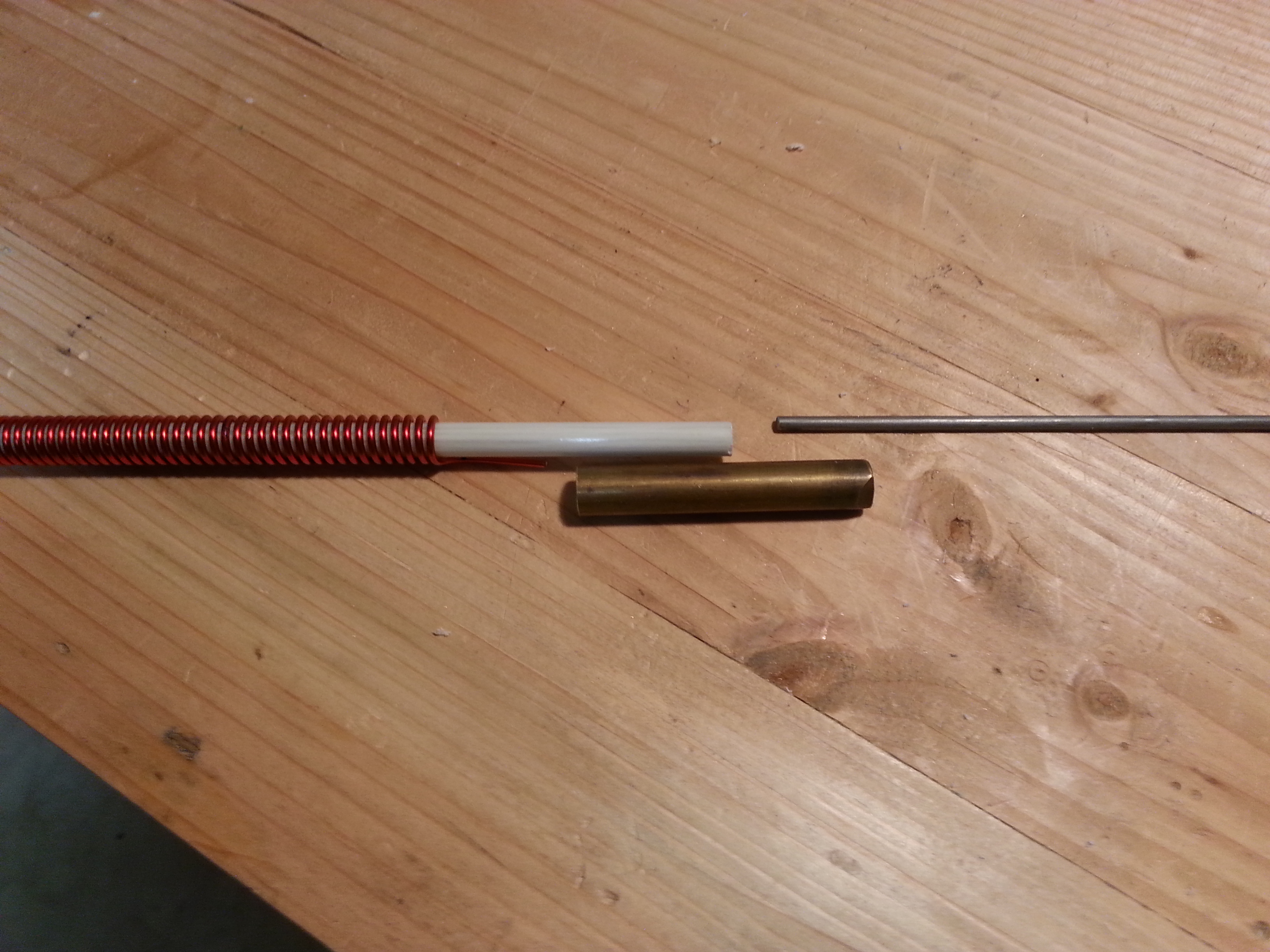
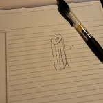
With this project I wanted to keep things as simple as possible and use off-the-shelf materials that are easily found and relatively cheap. One of the pieces I wanted was a simple piece of hardware I have seen many times. I have even bought it and used it, a three or four-inch long nut.  We used to use them for connecting CB antennas to rigid mounts with a nylon spacer block on the bottom and a bolt. The same basic format used to connect the spring mount base for mobile use. The intended use in this project is to connect the steel spike at the top of the antenna to the fiberglass body.

I remember buying these at Orchards Supply and Ace Hardware. I never had a problem finding one back in the 80s. Yesterday I went to OSH and Home Depot and the employees looked at me like I was from mars. They had these little 1-1.5 inch versions for connecting all-thread, which is what I am looking for, just longer. No clue. Nothing registered on their faces, even with the smaller version in my hand.

20150426_122018
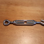
Anyway, the next closest thing was turnbuckle bodies. The “solid” bodies were aluminum and the open body type looked like nickel plate and galvanized. I ended up buying an open body style, but it really brought about several issues. First and foremost are the mechanical issues. The contact points on both ends are fairly small, less than half an inch. Even with the fiberglass rod and the steel spike screwed down all the way and touching there is still only a half inch of contact on either end.  These things are intended for stresses in tension not in bending which s what they will be exposed to in this application.

The next issue is the left-hand thread of one end of the turnbuckle. I was willing to deal with this I even started looking for a LH die to thread the fiberglass and this is where I decided to take a step back, reevaluate, and take stock of my options.

20150426_121813At this point the base end has been worked out. The right-angle conduit box is the base and will have 12 inches of half-inch PVC conduit inserted in the port that is parallel to the box. The wound fiberglass rod will be inserted through the PVC pipe into the base. I will cut off all but an eight-inch of the other port which will be the outside housing of the SO-239 which will be inserted from the inside of the box.

Once the antenna coil is soldered to the SO-239 on the inside of the box I will fill the box and the PVC pipe with polyester resin making the base a single solid weatherproof piece. The reason for the PVC pipe being 12 inches long  is to provide a solid place for mounting standoffs to be attached. All done with off the shelf hardware and materials with only one minor modification and no special tools.

Now back to the top end and mounting the steel spike to the fiberglass rod. The most direct method is using the all-thread nut I originally wanted to use. Since it is not available, and a sufficient replacement in size, complexity, and structural strength does not appear to be an off the shelf item, at least around here, I guess I need to make one.

I thought of welding nuts together and other welded configurations but they all require more work than what is really the simplest solution. Drill a piece of half-inch bar stock and tap it for 5/16″ 18 threads per inch. I already picked up the die, now I just need the tap and drill.

This solution does require a couple of tools, tap and die along with their respective handles, the right size drill (an F), and a little machining. This operation isn’t really a big deal. If you have a bench top drill press it will make things easier, but it can be done by hand with a bench vice.

The remaining decision is material for the threaded block. I know I have aluminum and I think I have both steel and brass that are the right size, or at least useable.  I am leaning towards the steel or brass. Aluminum and steel don’t play well together when there is the potential for moisture penetration between the surfaces making galvanic corrosion an issue as well as heat dissipation and mechanical contact issues.

More to come on this subject soon.

73,
~Jon KK6GXG

40 Meter Antenna

With the direct conversion receiver now working and tuned into the 40 meter band, it’s time to get to work on a better choice of antenna. The dipole would be great if it were in the proper environment, but this indoor, RF noisy environment is not conducive to picking up much.

Since tuning the receiver to the band I have been picking up both voice and cw transmissions but they are deep in the band noise. The other issue is portability. While the dipole can be pulled down and packed up for field use, it won’t work well in a mobile environment and would be a chore at home to pull down and put back up. So a whip makes the most sense for now. If the whip works at home I can wind up the dipole and keep it in the ready for field use.

Right now my focus is on getting the receiver, antenna, and any needed matching equipment in place. Once that is all together I can turn my attention to filters, amplifiers, and a transmitter.

Scan from the 1975 ARRL Handbook, page 606.

The antenna is a helically wound vertical that I mentioned in a previous post All Aboard the Project Train. I ordered a six foot fiberglass safety flag whip for the core and a fresh 1.5 pound spool of 14 AWG copper magnet wire to get the project going.

Yesterday I started the antenna construction by unrolling the 66.5 feet of copper wire and marking it every five feet, mostly so I didn’t lose my count. After dinner I started winding the coil onto the fiberglass in a tight coil. The picture in the header for this post is the fiberglass with about 30 feet wound on.

20150422_093128
66.5′ of 14 AWG copper wound onto a6′ x 3/8″ fiberglass rod

After winding the rest of the wire onto the fiberglass I threaded a dentists tool in between the wire wraps up the full length of the rod to create the uniform spacing for the coil.

On reflection at this point I think I might have opted for an 8 or 10 foot rod. For most applications it might be a better choice but neither would fit well indoors so 6 foot it is. I may build another antenna like this if it works well and try different lengths and diameters for different applications. A 10 foot whip would be better with a 1/2″ core and any longer would need 3/4″ or 1″ to remain stable unless it were placed inside a tube and filled with epoxy resin, another option. I haven’t tested any of these, I’m just spitballing with the structural integrity issue and weather resistance.

20150421_220832Now that the coil is done, the most difficult and time consuming part I think, it is time to move on to the spike and the base.

The plan for the spike is to pick up a small piece of 3/8″ copper tubing about 4″ long and use a coax crimping tool to mechanically center and attach a 1/4″ steel rod to about 2″ then sweat solder it together. After the spike is properly affixed, scoot the coil up a bit and solder the copper wire to the tube, add some epoxy inside the tube and scoot it back onto the fiberglass rod. This should give plenty of mechanical stability to both the spike and the rod as well as a good electrical contact. To help prevent galvanic corrosion I will coat the steel/copper interface with a few coats of lacquer.

The base is where I am going to have to think some more. The diagram calls for a variable inductor at the base of the antenna. I don’t think I will need this because I am planning on using an adapted Z-Match antenna tuning unit from chapter 23 of QRP Basics but that is for the next project.

OLYMPUS DIGITAL CAMERAIn the mean time I am thinking about using a PVC/ABS 90º conduit fitting with an access panel, cutting off and sealing up the right angle (on the bottom of the image), inserting the bottom of the antenna with the wire sticking up out of the box a little and filling the cavity with epoxy resin, leaving enough room to install an exterior lug fitting to attach the wire to on the inside.  For mechanical stability and to provide a secure mounting point I was thinking about using 6″ of conduit around the antenna and filling that with epoxy resin as well.

I hope to get the spike done this week and the base over the weekend. While out and about getting the final parts for the antenna I will be hitting HSC for the parts for the Z-Match. Another busy week for radio. 🙂

73,
~Jon KK6GXG