With the direct conversion receiver now working and tuned into the 40 meter band, it’s time to get to work on a better choice of antenna. The dipole would be great if it were in the proper environment, but this indoor, RF noisy environment is not conducive to picking up much.
Since tuning the receiver to the band I have been picking up both voice and cw transmissions but they are deep in the band noise. The other issue is portability. While the dipole can be pulled down and packed up for field use, it won’t work well in a mobile environment and would be a chore at home to pull down and put back up. So a whip makes the most sense for now. If the whip works at home I can wind up the dipole and keep it in the ready for field use.
Right now my focus is on getting the receiver, antenna, and any needed matching equipment in place. Once that is all together I can turn my attention to filters, amplifiers, and a transmitter.
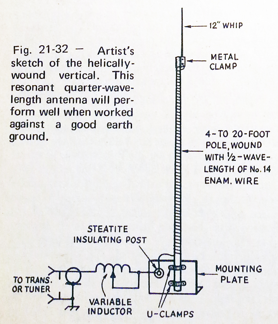
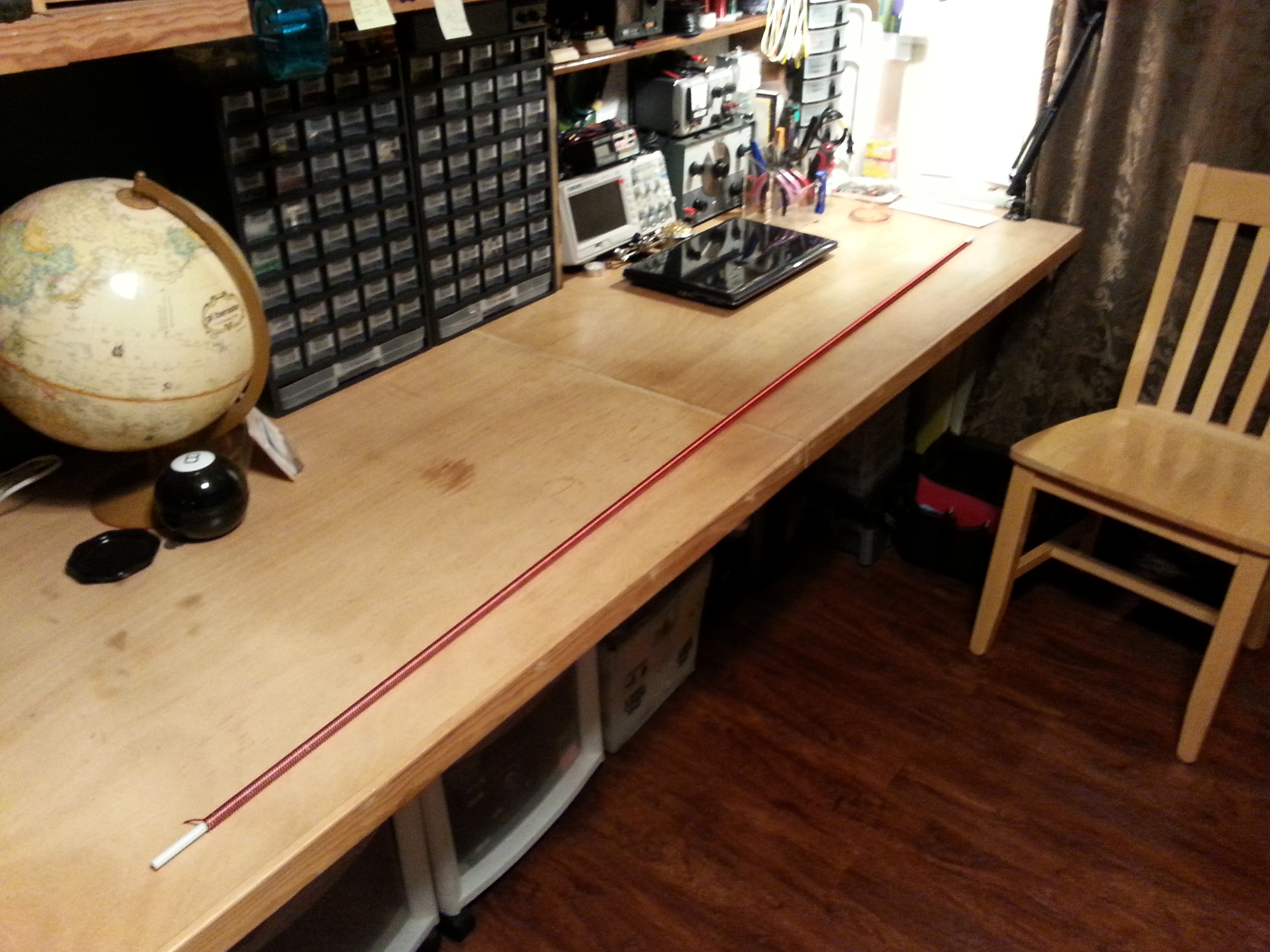
The antenna is a helically wound vertical that I mentioned in a previous post All Aboard the Project Train. I ordered a six foot fiberglass safety flag whip for the core and a fresh 1.5 pound spool of 14 AWG copper magnet wire to get the project going.
Yesterday I started the antenna construction by unrolling the 66.5 feet of copper wire and marking it every five feet, mostly so I didn’t lose my count. After dinner I started winding the coil onto the fiberglass in a tight coil. The picture in the header for this post is the fiberglass with about 30 feet wound on.
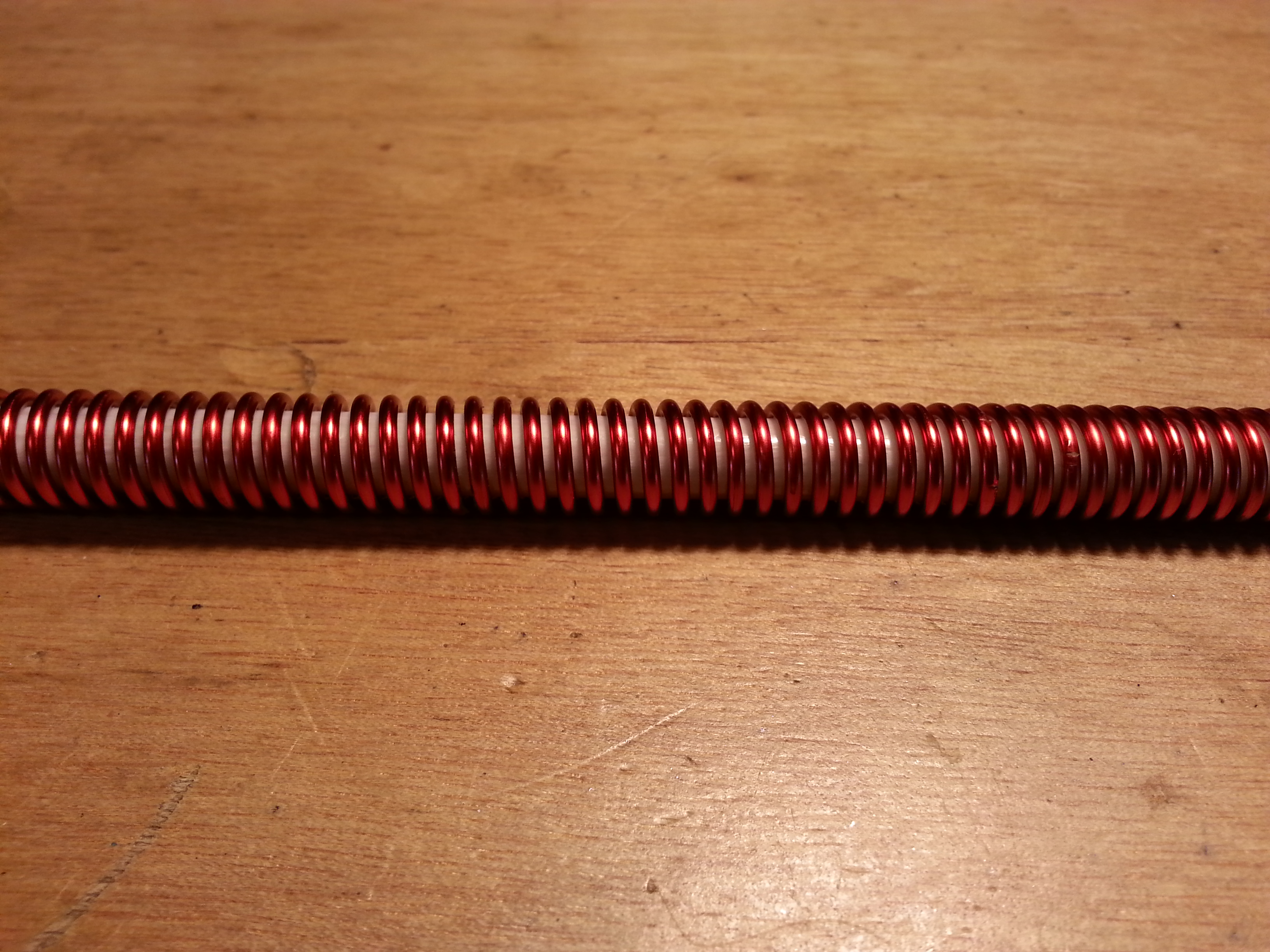
After winding the rest of the wire onto the fiberglass I threaded a dentists tool in between the wire wraps up the full length of the rod to create the uniform spacing for the coil.
On reflection at this point I think I might have opted for an 8 or 10 foot rod. For most applications it might be a better choice but neither would fit well indoors so 6 foot it is. I may build another antenna like this if it works well and try different lengths and diameters for different applications. A 10 foot whip would be better with a 1/2″ core and any longer would need 3/4″ or 1″ to remain stable unless it were placed inside a tube and filled with epoxy resin, another option. I haven’t tested any of these, I’m just spitballing with the structural integrity issue and weather resistance.
 Now that the coil is done, the most difficult and time consuming part I think, it is time to move on to the spike and the base.
The plan for the spike is to pick up a small piece of 3/8″ copper tubing about 4″ long and use a coax crimping tool to mechanically center and attach a 1/4″ steel rod to about 2″ then sweat solder it together. After the spike is properly affixed, scoot the coil up a bit and solder the copper wire to the tube, add some epoxy inside the tube and scoot it back onto the fiberglass rod. This should give plenty of mechanical stability to both the spike and the rod as well as a good electrical contact. To help prevent galvanic corrosion I will coat the steel/copper interface with a few coats of lacquer.
The base is where I am going to have to think some more. The diagram calls for a variable inductor at the base of the antenna. I don’t think I will need this because I am planning on using an adapted Z-Match antenna tuning unit from chapter 23 of QRP Basics but that is for the next project.
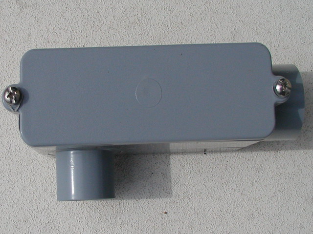 In the mean time I am thinking about using a PVC/ABS 90º conduit fitting with an access panel, cutting off and sealing up the right angle (on the bottom of the image), inserting the bottom of the antenna with the wire sticking up out of the box a little and filling the cavity with epoxy resin, leaving enough room to install an exterior lug fitting to attach the wire to on the inside. For mechanical stability and to provide a secure mounting point I was thinking about using 6″ of conduit around the antenna and filling that with epoxy resin as well.
I hope to get the spike done this week and the base over the weekend. While out and about getting the final parts for the antenna I will be hitting HSC for the parts for the Z-Match. Another busy week for radio. 🙂
73,
~Jon KK6GXG