Tag Archives: 40 meter

New-To-Me Signal Generator

120 kc (kHz) to 200 mc (MHz)

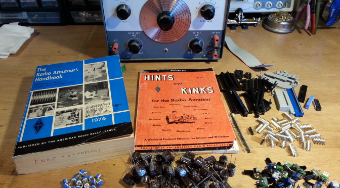
On Saturday I picked up a few things at the De Anza Electronics Flea Market. The most impressive acquisition would be the Lafayette Signal Generator for $20.

I have been needing one and I was dreading the prospect of having to build one and having a tough time without the right tools for calibrating it, so this was a great find and a steal of a value, though I didn’t know it for sure until today.

One thing I have learned about buying used electrical/electronic equipment, particularly in at a flea market, is that you have to take your time and open it up, get documentation, inspect and clean the equipment before attempting to use it, or plug it in for that matter.

20150414_075130 
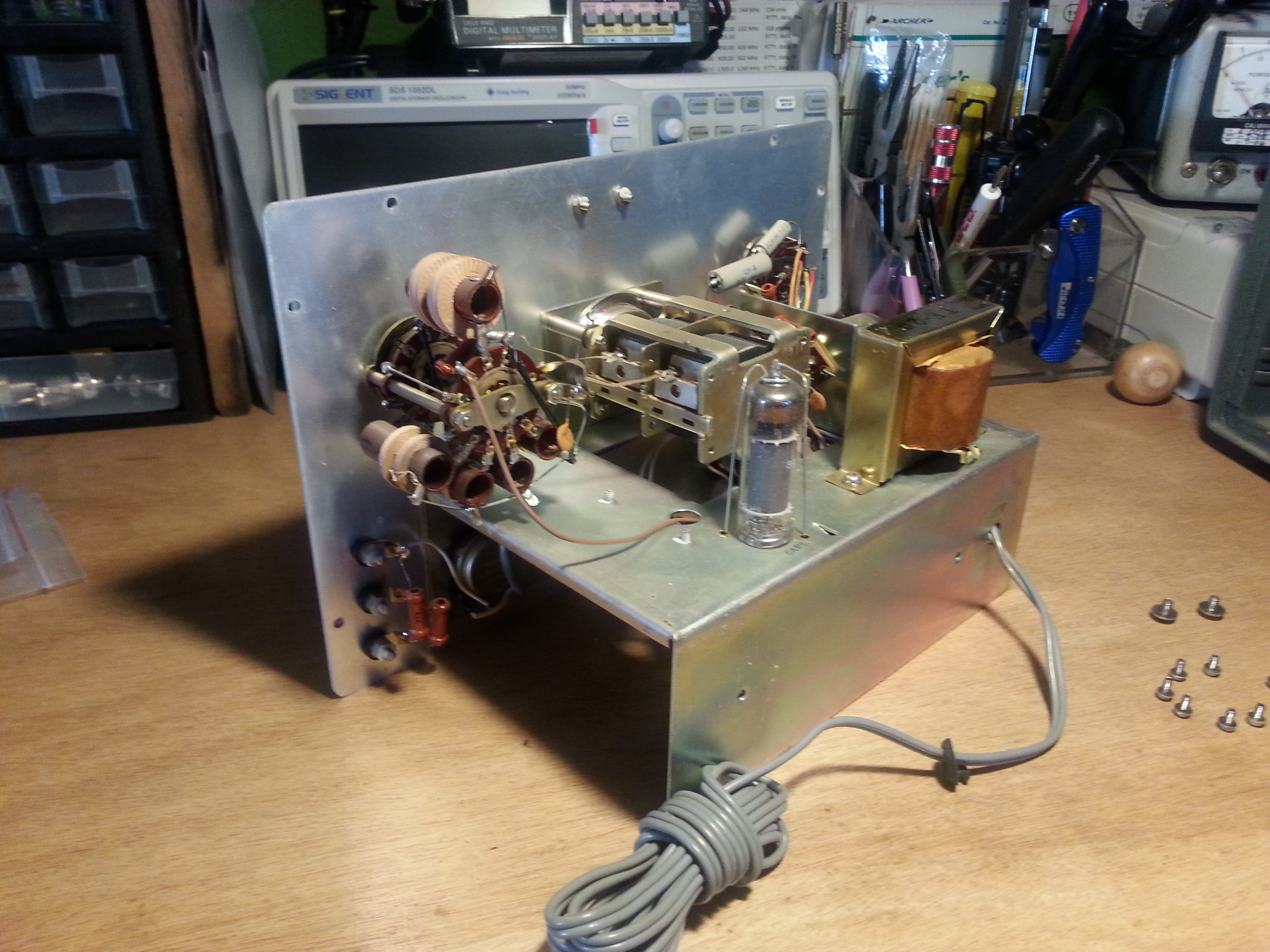
Sunday was opening day. I noticed right away that I would need to replace the power cord grommet as it was in two pieces. I didn’t actually get to anything else until today.

Today I inspected all of the wiring and components, looked for hot spots and anything that would indicate an over heat. Having found nothing of the sort I moved on to cleaning, which there was surprisingly little to do. I made sure the tubes were cleaned and had no fingerprints on them. Now that I have a piece of tube equipment I will need to get a tube tester. 😉

With the cleaning done it was time for the plug-in and smoke tests. No pops and and no smoke! I let everything warm up and burn in for a good twenty minutes before starting any tests.

Testing with the oscilloscope began with the AF (audio frequency) side of the generator. After the twenty minute warm up period the “approximately 400 cycles” audio tone as specified in the manual turned out to be stable at 388 cycles (Hertz). I can work with that.

“kc” is kilocycles. The term is essentially the same as the more familiar kilohertz along with “mc” megacycles being the same as megahertz. The change over in terminology occurred slowly from the mid 70s to the mid 80s. Many hams still use kc and mc. I use them interchangeably depending what I am referencing or who I’m talking with. This piece of equipment has frequency labeled on the dial as kc and mc.

20150417_152319
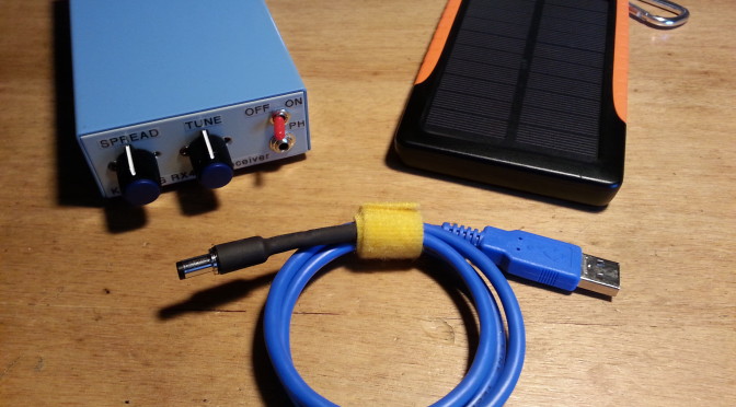
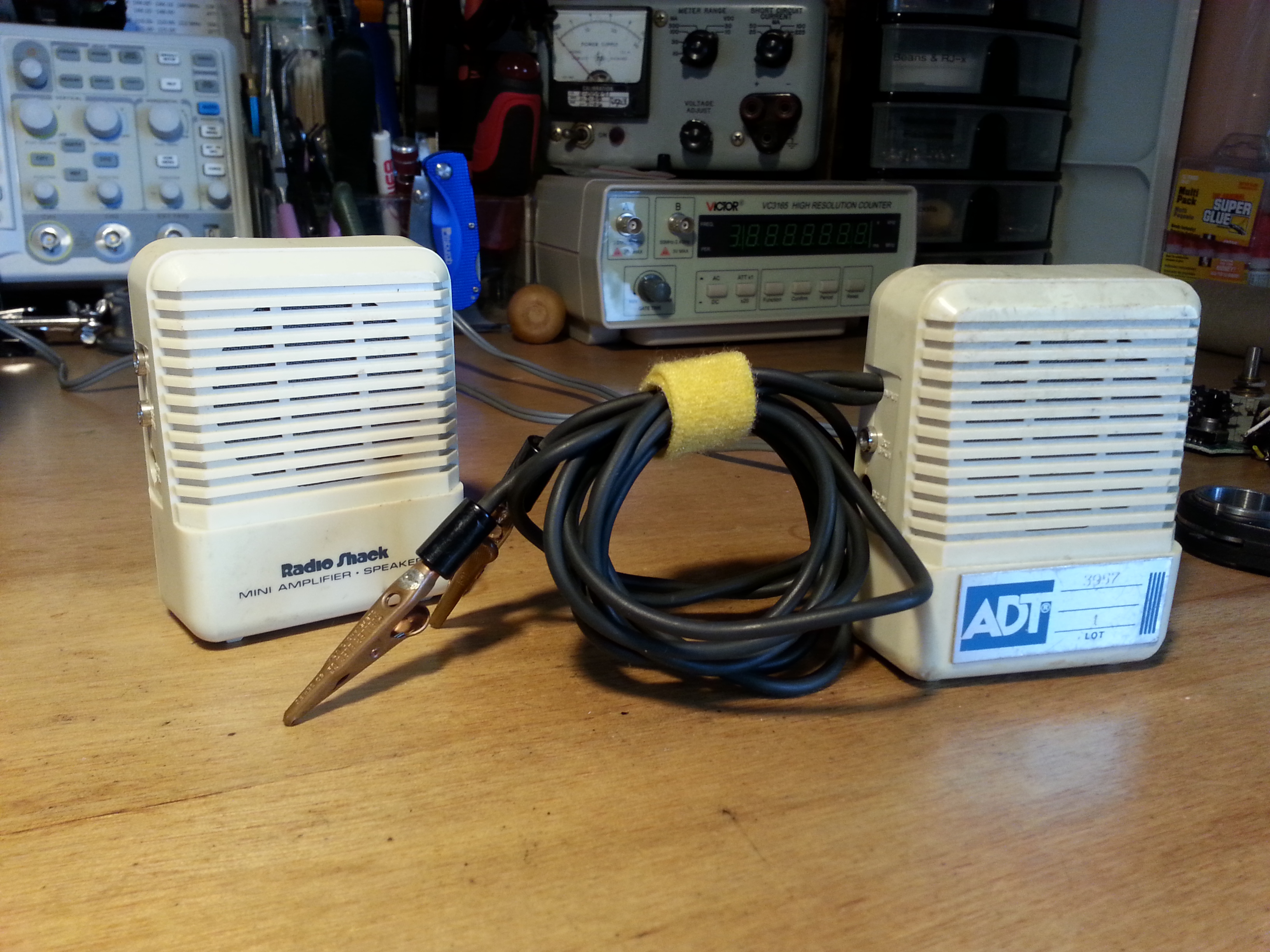
Moving on… The generator did its first diagnostics job with a portable amplifier I have had for a very long time (the one on the right). I clipped on the amp to the audio out and it turn out the volume control on the amp is trashed from banging around in my tool bags for a couple of decades so I will need to replace the potentiometer in that this weekend.

I then moved over to the RF (radio frequency) side of the generator and clipped on the oscilloscope. The RF side is divided into 5 switchable bands. I checked each band by referencing the frequency on the dial with the frequency on the O-scope. All five bands checked out very closely to the dial. A little lead or lag here-and-there, but overall pretty close for this equipment and its age which I’m guessing is about as old as me (made in the mid/late 60s).

20150417_152206The frequency counter I purchased last year has been giving me problems. New equipment, cheap (figuratively and cost), and no manual. With the help of the new sig gen and the oscilloscope I managed to fix a couple of minor problems and figure out the modes on the counter in the process. Looks like the electronics bench is finally coming together.

Now that I can check the receivers I build I can also check the transmitters I plan on building. I can also check portions of the radios as the construction moves forward. I plan on building more of my own test equipment but it’s nice to have a reference point or two to calibrate off of.

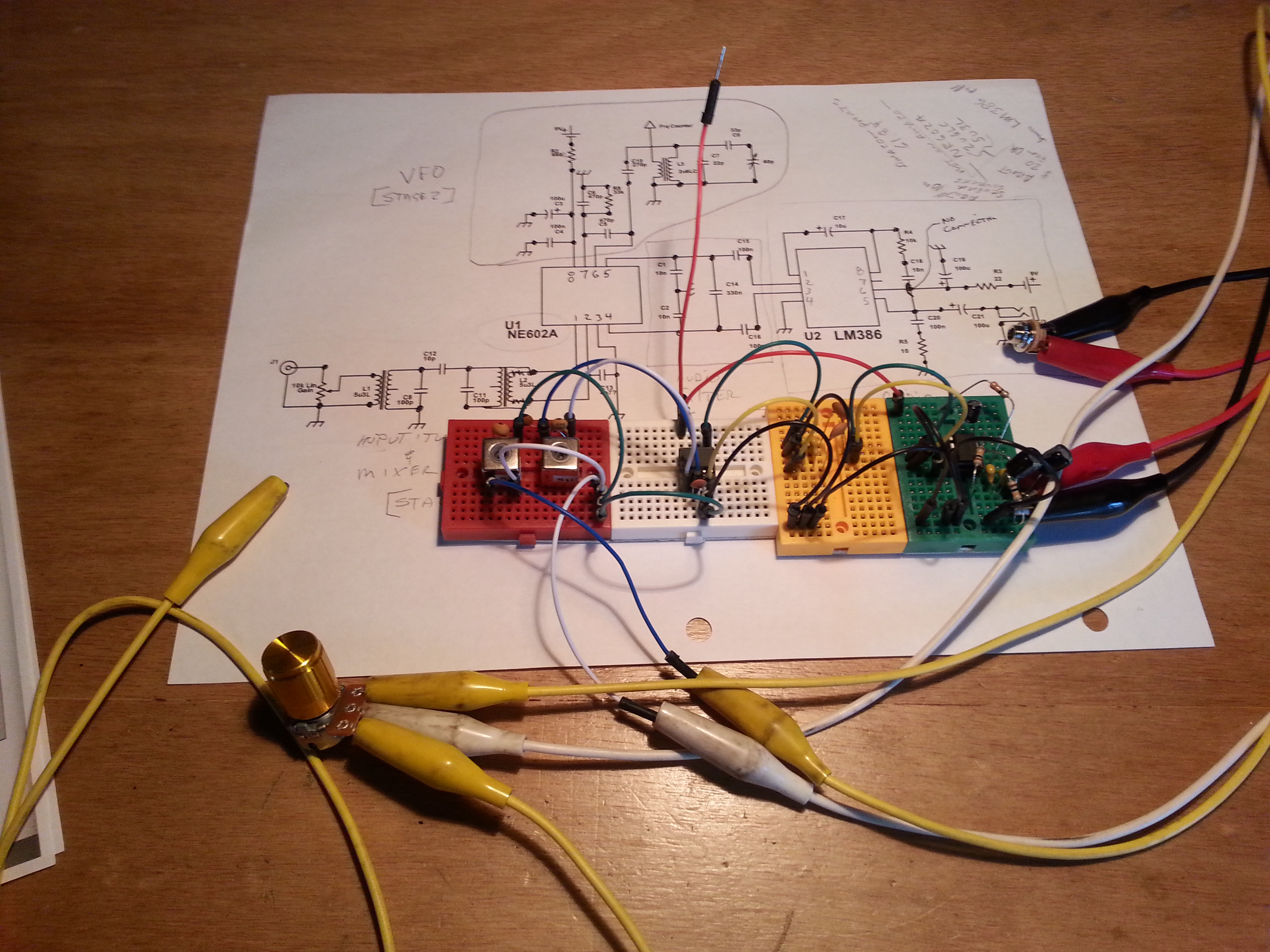
I also did some diagnostics on the 40 meter direct conversion receiver project and updated the project page… some very interesting results, you should take a look. 🙂

A productive day I think.

73,
~Jon KK6GXG

All Aboard the Project Train

Sometimes it is indeed a project train, not just a project; occasionally a train wreck, but it’s early so we’ll hope for the best.

Now that I have built several receivers and a transmitter for 40 meters, I probably should have an antenna that does more than pick up all the RF noise around the shack. The antenna, and I use the word loosely, is nothing more than a dipole of 26 AWG insulated wire strung around the house. While it might work well if the wire was straightened out on a hill top, or even in a backyard, elevated 15 feet or more above ground, in its current incarnation, in a word, it sucks.

Next up on the project block, an antenna, sort of…

I have been looking at several small footprint antenna options like spiral coils that look like those God’s Eye yarn and popsicle stick things you may have made as a kid,  the one in the movies from the 40s when the resistance spy transmitting Nazi secrets and the SS storms in. It looks like a X and has thin wire wound around it.
288And Small Loop antennas that look more like old direction finding antennas on aircraft. And by the way, according to the formulas and general information, for 40 meters, not so small, 10′ diameter.

Now there are lots of variations and tons of experimental configurations to run with, and I do want to play with many of the possible configurations, but I need a stable, small, portable option for the immediate future. Something I could mount on the car, throw up on a pole, or stand up on the back porch, all without much effort. I also need to keep the cost down.

Scan from the 1975 ARRL Handbook, page 606.

Enter the Helically-Wound Short Vertical. I ordered some 14 AWG lacquered copper magnet wire and a 72″ long 5/8″ diameter fiberglass rod, I need to learn to make these so I also ordered a How-To book on making composite fishing rods, and I’m in $20 so far. I have all of the hardware items including the 12″ spike for the top. What I don’t have is the variable inductor, or a tuner.

Whooooo Whooooo! Here comes the train.

RollspuleLets start with the one I haven’t done any research on yet, the variable inductor. The mechanics are fairly simple, rotate the coil and the follower moves up and down the coil creating a tap point. As long as the coil is perfectly cylindrical, the follower makes good contact, and smoothly moves down its axis rod, no sweat. he he he, no sweat I only need the one variable inductor according to the diagram so I really need to find out what value I need. I already have several small value iron-core variable inductors so I may not need to make this one, but if I do, it will be a homebrew. These things are a high-dollar item otherwise.

Moving on to the antenna matching unit. I have plans for one that is fairly simple and straightforward, I even have most of the parts on hand. What I don’t have is the variable capacitors. Sensing a theme here? Variable…

cav-167-205-71_lgBA funny coinky-dink on capacitors; while I was doing research on the Small Loop antennas I came across several websites that went into some lengthy discussions on making variable caps. Turns out, they aren’t that hard to make, I even have nearly all of the materials to make several. Not only are they fairly easy to make, but the formulas for calculating the capacitance based on the area of the plates, number of plates, and the distance between the plates is also fairly straight forward.

So lets see where we are now…
I have three receiver and one transmitter for 40 meters. There is an antenna for them, but it sucks particularly in this location. My next project is to build another transmitter, But I will need a better antenna first…

  1. Antenna
  2. Resonator for antenna (variable inductor)
  3. Antenna tuner
  4. Variable capacitors for the tuner

Now, after these are done I can move on to the new transmitter. As a side note, with the next transmitter project I wanted to pump up the power all the way to a couple of watts, not just miliwatting it. I also want to include SSB (Single SideBand, voice) as well as CW so I can incorporate digital modes into the shack. For all of this the antenna really needs to be better than what I am using.

That’s all for now, 73,
~Jon KK6GXG

40 Meter Loose End

20150410_115049Today just started off good. The post came early and an expected package came a few days early, my QSL card order from Vistprint.

I’m not quite sure when I will need to send any out, but now I have them and I am very happy with how they came out. I’m also very proud of them, I spent the better part of a day working on the layout and confirming the text-safe areas around the card. The finish product is just what I was hoping for.

20150408_154753A couple of days ago I got a package in the post from another ham, Brad  (AA1IP) and oh my, what a box it was. A medium sized  USPS Priority Mail box filled to the top with stuff.

I started sorting it out that evening and last night and again this morning. Its all sorted into like or similar components. There is still a lot of sorting to do, particularly with resistors and capacitors. Among the jumble there were a few packets of resistors already sorted by value and those are my project for tonight. Get them all stowed away.

20150408_162644The sorting process will take a while and I’m in no rush, so bag by bag over time it will all find homes. Once I get everything stowed I may ask for another. Mmmm, a masochist, I am *in my best Yoda voice*.

A small follow up project got completed over lunch today. I finally finished the power cable for the 40 meter receiver I built. The original plan was to build the receiver and a follow up transmitter, package them together, and power them both with a solar charger / battery pack. Also in the original plan was to build out the cable from scratch.

Funny thing about plans… I dont have any good multi-conductor cable anymore. The closest I have is some cat 5 and some twisted-pair for telco work. Nether is appropriate for this project. I was waiting to go to the Electronics Flea Market @ DeAnza this weekend but I also have plans to go to a radio builders club meeting on Sunday and check things out there. I was encouraged to bring my project along, and since the build was complete I thought I should power it as planned.

20150410_132528Long story short, I know, too late, I decided to pull an extra USB printer cable out of my computer junk box and use an existing cable, clip an end, and install the power plug. Easy peasy.  The plug isn’t quite big enough for the cable but I adapted it and heat shrunk that end for some extra stability. Thoroughly checked it for shorts and opens twisting it about and we are good to go.

The radio can now be powered by a computer, USB car adapter, or the solar power supply I had originally intended to use. Any standard USB source with the appropriate 5 volts will do.

I’m sure I’ll have more to post about after the Flea and the club meeting.

Until then, 73,
~Jon KK6GXG


BreadboardRadio Kits

Breadboard Radio KitsOn Wednesday I received some awesome mail, the kits I ordered from BreadboardRadio.com arrived! As I am inclined to do, I opened things up and began organizing and inventorying the contents there in. Counter to the habits of a younger Jon, I printed all of the distructions, what I tend call them, and read them all, cover-to-cover. Even before setting up the first project!

I completed the electronics of the Matchstick antenna tuner Wednesday evening. Without a receiver or transmitter I couldn’t do much with it. Yesterday I finished the electronics of the Sawdust regenerative receiver and proceeded to spend over four hours tuning up and down the 40 meter band.

There was some broadcast, not sure if it was AM bleed or SW though I am leaning towards SW, phone (voice), and some digital transmissions. I believe I heard both RTTY (Teletype) and PSK31 (ASCII keyboard-to-keyboard). No CW though. I was really hoping for some Morse Code. Lots of band noise. The solar storm this week is making for some interesting sounds.

Progress shots were taken and will be uploaded to the usual places, here, G+, and Flickr, but I wanted to get them all wrapped up nice and purdy first. Because they are kits and will be done over the weekend most likely, I figured it was worth the wait. I am going to post about each kit separately though.

When I said a kit was completed, I deviated from the distructions in one respect. They called for finishing the wood bases before the electronics so the mounting of said electronics goes directly onto a clean, freshly finished mounting. Well, I didn’t do that.

Matchstick antenna tuner kit from BreadboardRadio.com

I wanted to finish all of the bases at the same time… and, okay, I wanted to get a radio on the air ASAP. So, yes I will finish the bases, but it will be all at once. I I am not sure with what finish I will be using so for now the kits get mounted on the raw base.

Before the kits arrived I built a simple ½  λ dipole to have something to test the radios with, and it does work, but I don’t like the feed point or the wire spools. I didn’t take any pictures because, well I’m not particularly proud of it. That may sound vane, and it is, but some hack jobs just shouldn’t have pictorial evidence.

To resolve the antenna issues and to address the bases for the the kits I think a little fabricating shop time is in order. This morning I am designing the feed point / spools and after day-job stuff I will look at finishing materials for the kits.

73,

~Jon KK6GXG

40 is dead, long live 40!

I had mentioned a little while ago that I was planning to work on a 40 meter receiver followed by a 40 meter transmitter. This is still the plan but there was a snag that I thought was worth mentioning, particularly for those new to Amateur Radio or to homebrew radios.

The 50 Ohm 5Watt dummy load I built last month, and most of the diagnostics tools I have been building recently for that mater, came from the book QRP Basics, second edition by Rev. George Dobbs G3RJV.  Another project in QRP Basics is the 40 meter (7-7.3 MHz) receiver I planned to build. The receiver in the book has some additional modifications to the RF (Radio Frequency) input section, an RF band filter and a modified tuner that replaces the VXO (Variable Crystal Oscillator) with a VFO (Variable Frequency Oscillator.) The VFO has a wider tuning capability, it can tune the entire band rather than 600-700kHz of the band centered on the crystal frequency in a VXO.

First go at the 40
First go at the 40

The diagram made sense, for the most part, and I could see and define the separate sections of the receiver. The challenge was my minimal knowledge of circuit diagnostics.

I got the AF (Audio Frequency) amplifier working fine. Likewise the AF input filter. It was the RF side of the equation that was giving me trouble.

It was clear that I needed to improve my skills in diagnostics so I picked up a copy of Experimental Methods in RF Design by Wes Hayward W7ZOI, Rick Campbell KK7B, and Bob Larkin W7PUA, here after referred to as EMRFD, with hopes that it would give me the information I need to better approach the radio build projects I have planned. Just 8 pages into the first chapter and it is making me think and work!

The receiver I originally planned on, and started, was from QRP Basics. A stripped down basic variation of this receiver is the first project in EMRFD starting on page 1.7. The nice thing is that this design has fewer parts, a VFO that uses a LC (an inductor capacitor network circuit) tuner that gives you the whole band, approximately 6.9MHz to 7.5MHz, best of all the complimentary transmitter is also in the first chapter.

EMRFD makes you think more about what you are doing and requires you to actually learn about each circuit segment. The first chapter outlines a very modular approach, the building blocks of the larger picture but in reverse. Start big with simple broad strokes, then narrow it to more manageable chunks, then further and further as you go. It encourages the start simple philosophy to get it working, then refine individual areas as you go.

The book goes on to give a more in-depth look at specific RF circuits, not a list of projects though, it gives you an idea as to how various RF circuits may be improved or incorporated into a design to improve the over all performance of a project. It seeks to instill an adventurous and experimental approach to RF design. Rather than a “you must” approach it is a “hay, what if” way of looking at overcoming the challenges in RF design work.

QRP Basics is a great book, and it covers homebrew radio, but more as a kit builder and operators guide rather than a circuit designers/builders guide which is what I am really looking for right now. I don’t see myself getting an electrical engineering degree, but I do need to up my game in RF circuits and basic electronics knowledge, big time.

Second go at the 40
Second go at the 40. Parts poked into an anti-stat mat grouped by receiver segment, RF to the left and AF to the right. Look at those sexy toroids!

About the title of this entry… Yesterday I completely disassembled the receiver I started two weeks ago and restocked all the parts.  The 40 is dead. Today I poured over the schematic of the EMRFD design and began picking the parts and planning the layout. Long live the 40!

While part of the goal of EMRFD is to use whatever parts you have lying around, I was going to have to make some weird choices in parallel and series multi-value/component clusters and I am not yet up to the challenge of re-designing things like LC tuning circuits so it was also shopping list time today as well. With a bit-O-luck HSC will have the variable capacitors, resistors, and jacks I need finish this project quickly.

My neatnic brain is not ready to go with “ugly” construction so my boards, at least for now, will be done on perf-board.  I know “ugly” is a perfectly acceptable prototype process, and has benefits in VHF/UHF/SHF frequency applications, but I am working in HF so a little attention to not building in inductive ground planes should be fine. My aversion to “ugly” includes using two 100 ohm resistors in series when I don’t have a 200 ohm resistor. I’m sure I will get over this affliction at some point, I’m just not there yet. In the mean time I will spend a little more time on the layout phase.

Until tomorrow the 40 is on hold. The plan is to have it up and running before April. I have a lot of projects to do this year. 😉

73,
~KK6GXG

ETA: 2015-04-03 The new project page for the EMRFD 40 meter receiver is here.

Flickr photo set for the 40 meter receiver

My first homebrew toroid inductor. Aint she purdy?