Tag Archives: 40 meter

Solder-less Progress

Some good stuff got done this week even though I didn’t melt much solder.

I had an amateur radio testing session on Saturday. It was a busy day with lots of new hams passing there Technician, some going on to pass the General exam, and even an Extra! We also had several upgrades to General and Extra.

For me the session was also a good learning experience as a VE because I had the opportunity to get some training in another job with the group.

We basically have three jobs split among the VEs present at any given session; two administrative jobs, and a panel of test examiners.  I have been participating as an examiner for the last several months. Today I received some training for the administrative side of things.

I have been putting off the testing on the Beach 40 until I get the last few details finished on the audio and RF amps as well as the LP filter. This week I am playing beginning of the month catch-up with the day job so time is short.

Also tied to everything else is the change over from Windows to Linux. I have deleted the Win partition on the laptop and am now running full on Linux. I am loosing two programs I liked but just couldn’t get them to work with Linux native or emulated and I don’t want to run virtual machines. I still have all of the data, and I do have a Windows 7 laptop in the shop I basically only use for the web browser.

The programs I am loosing are Quicken and Business Plan Pro. BPP will just go away. I exported all of the business plans I have put together over the last decade to .doc files which I can access through OpenOffice. I can use the previous plans to build new ones as needed in document formats.

Quicken is the one giving me headaches. Supposedly you can export the data to a file for import to Skrooge. No joy. After several exports and several hours I made the contagious/stupid decision to just go back and reenter all the data for this year.  It sounds a lot worse than it is. I will just do one month at a time and by the end of this month I should be all caught up. Not to mention very familiar with the new software.

I have found replacements or versions that will run on Linux or in emulation for all of my radio software an in fact found some new stuff that looks mighty interesting. Big plus here.

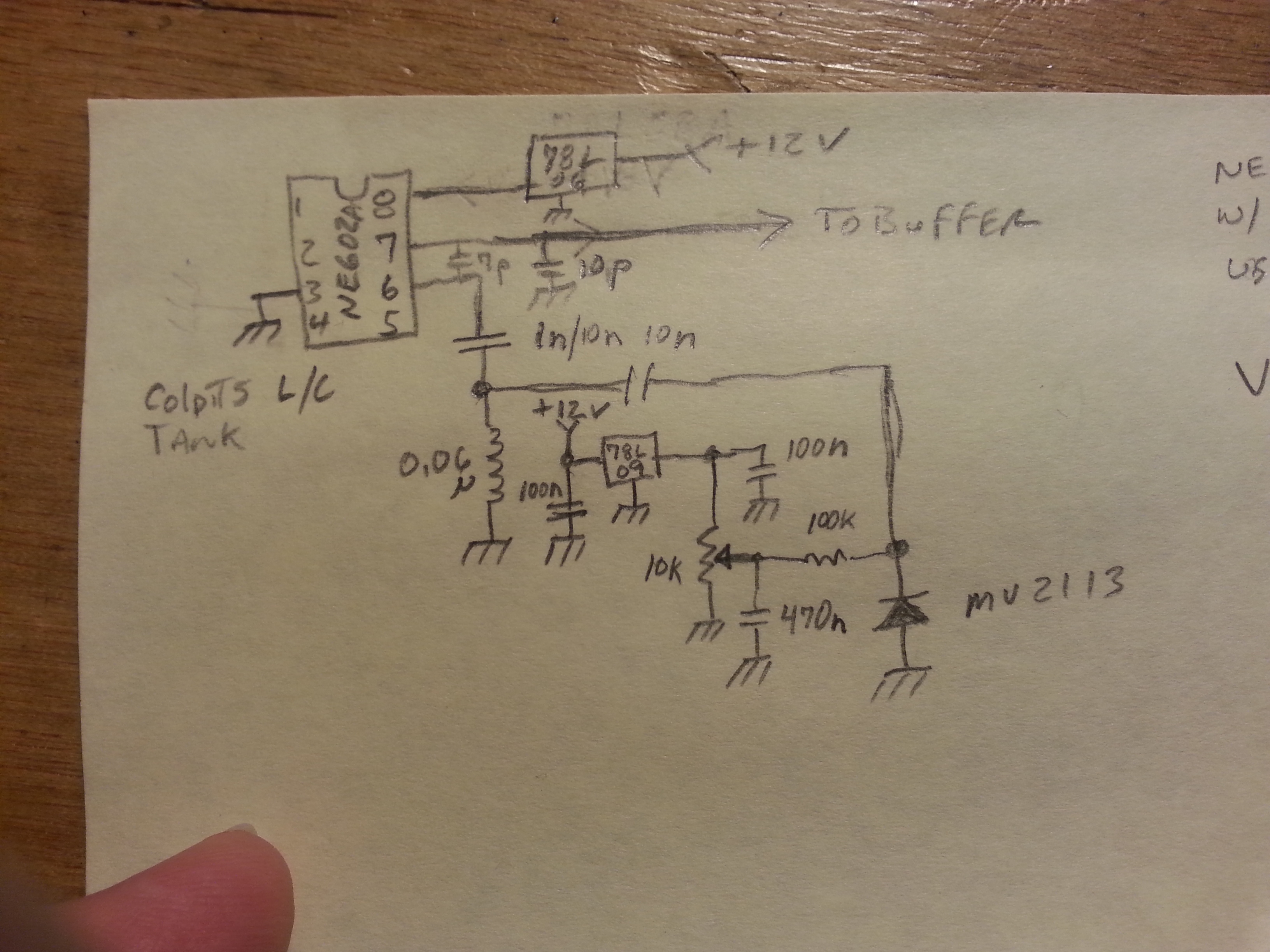
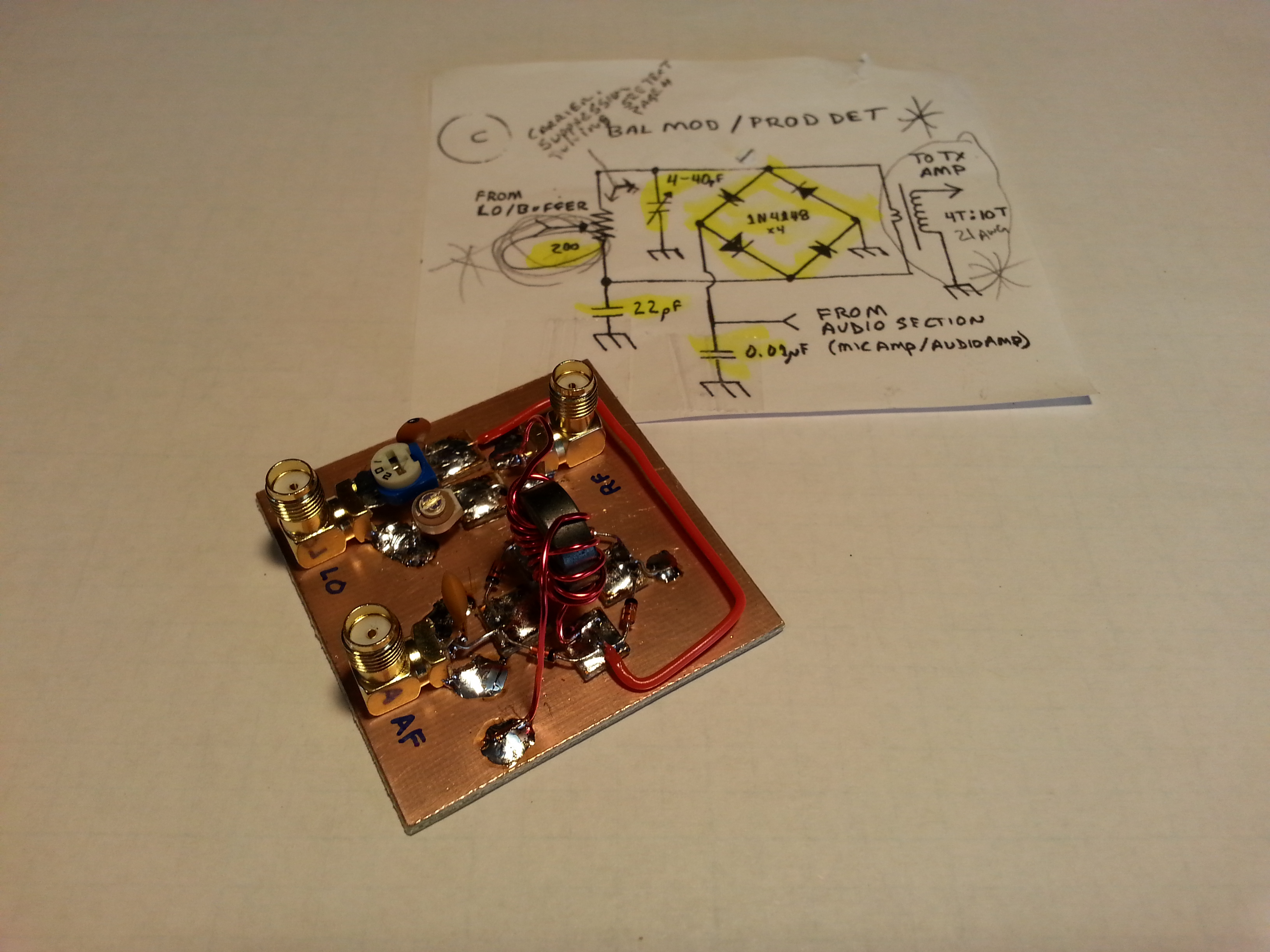
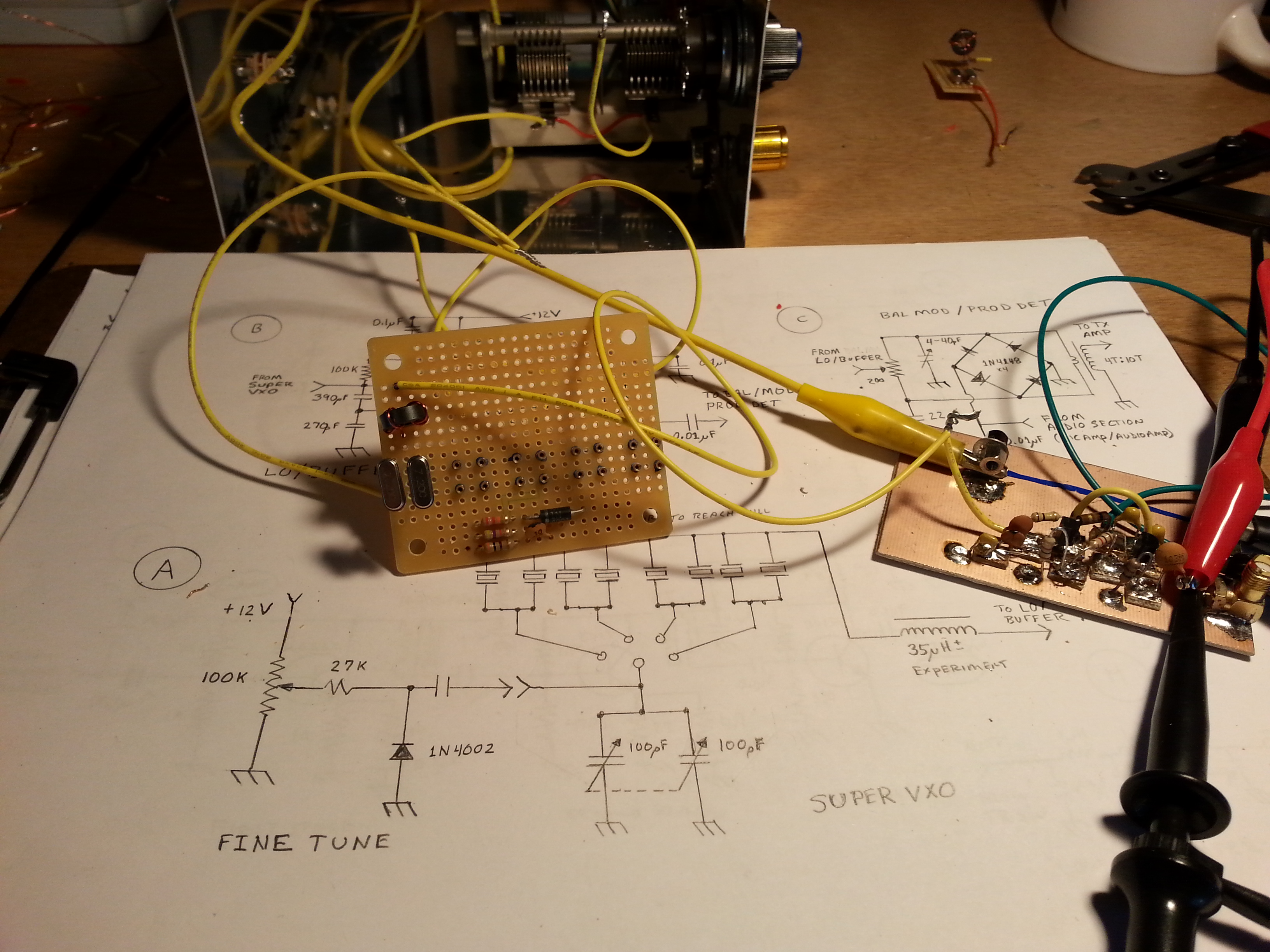
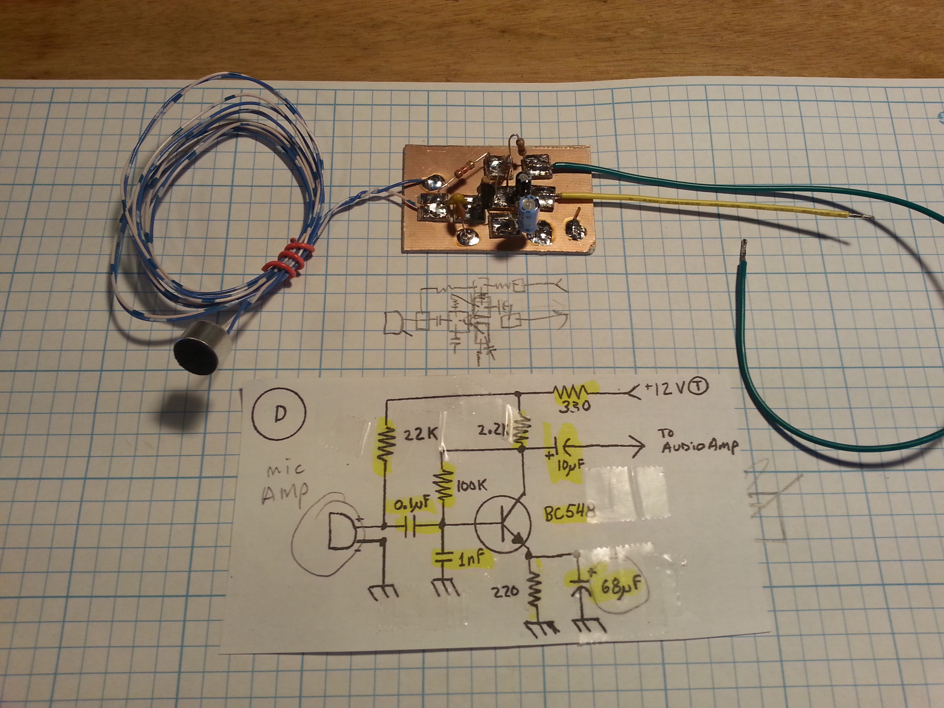
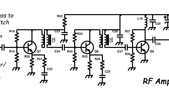
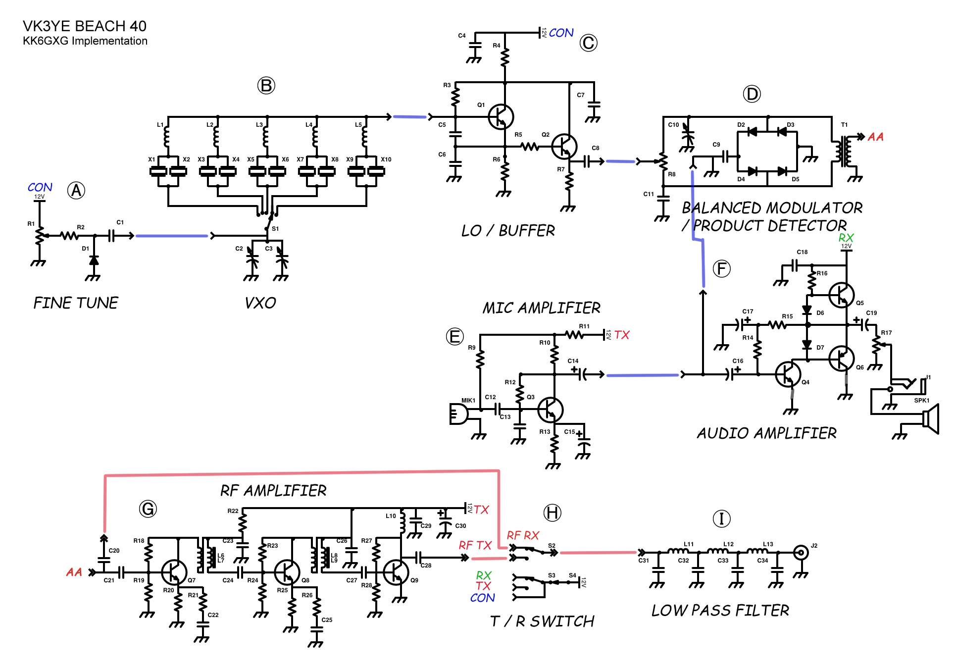
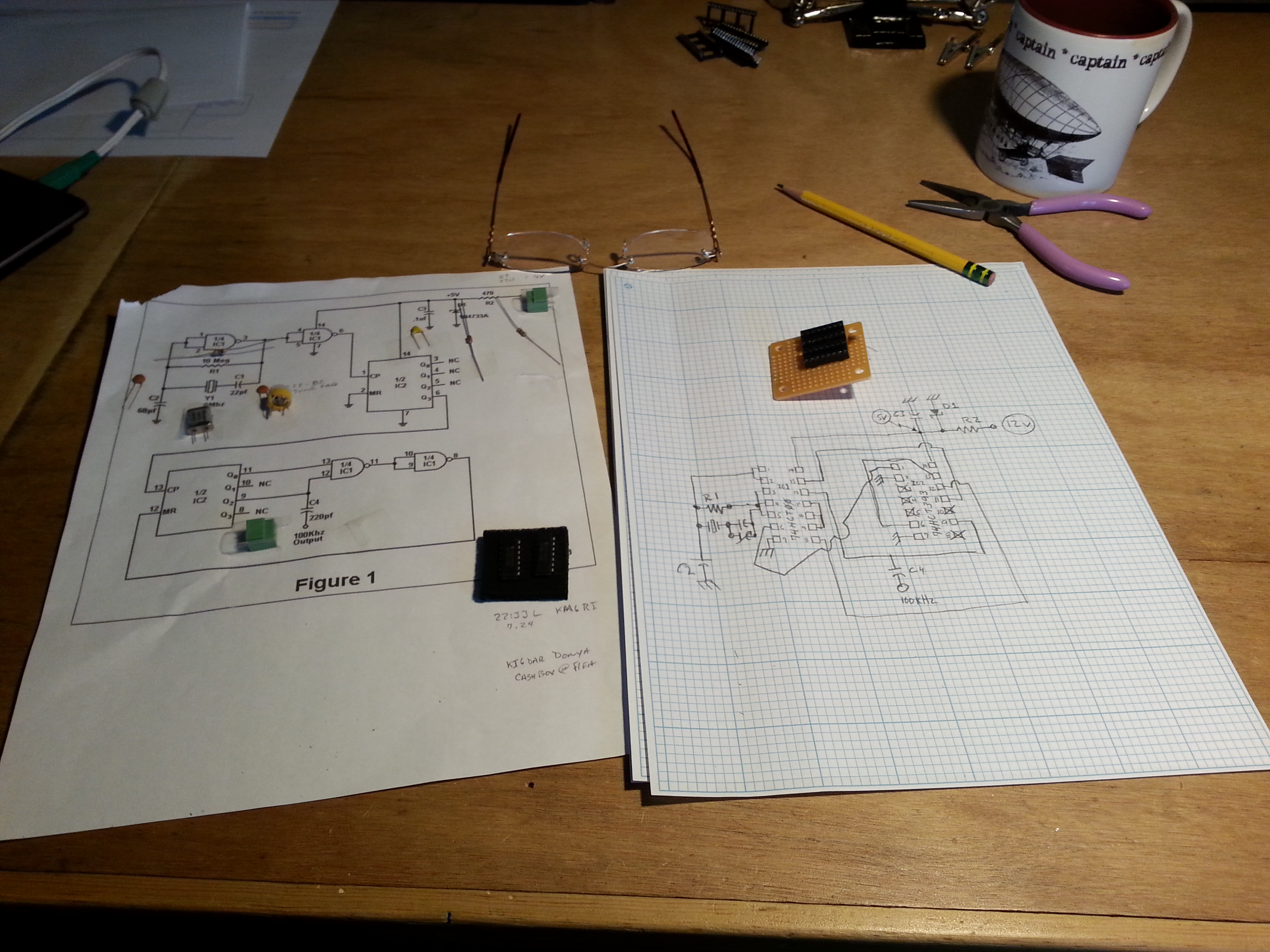
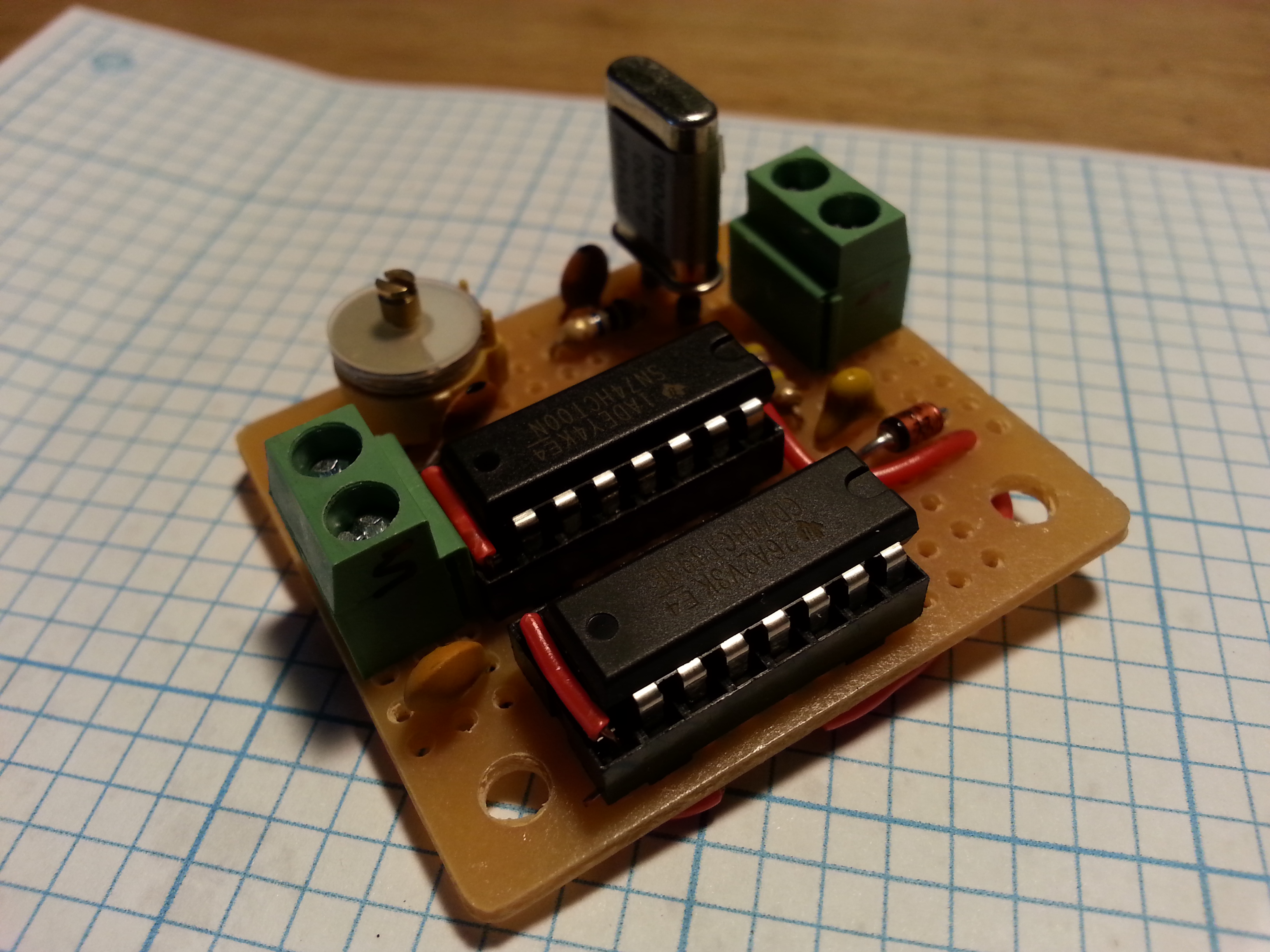
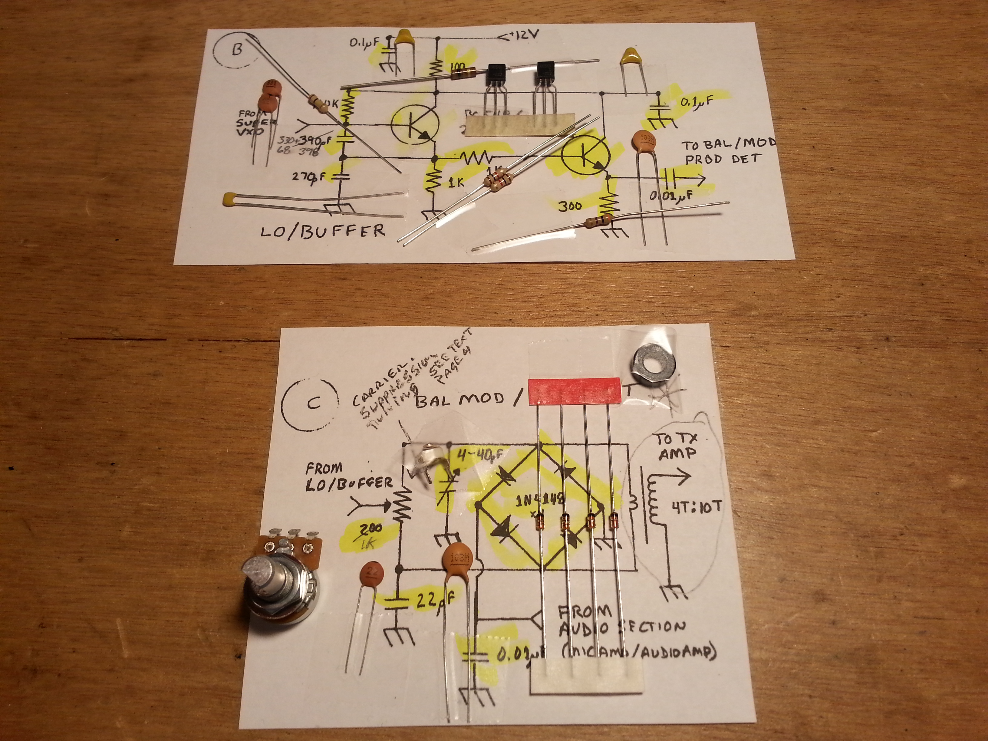
Along with the radio specific software, I found gEDA Schematic Editor. WOOT! It took a little getting used to the interface and component placement, but I like the results a lot. I have been redrawing the schematics I originally did on schematics.com for the Beach 40 and think they look much better. I will be posting them soon to the build page. A good thing too because there are some errors on those schematics. Ooops!

One last update before I go, I was working on test prep for my commercial radio license a while ago but got sidetracked by all of the build projects and the day job. One of my goals for second/third quarter is to take my commercial radio exams, at least two of the three anyway, and get my commercial license. So I will be committing some of my limited time to that endevor over the next few weeks. The build will continue, I still hope to have the Beach 40 up by Field Day, but I need to budget more time to the Day Job/Future Day Job.

Anyway, I have 0.5TB of files syncing with Google Drive and a pile of accounting stuff that needs to find a new home in Skrooge so that’s it for today.

Until next time, 73,
~Jon KK6GXG

Back to the radio

KK6GXG-MakingWavesTo keep domestic peace I have not been building on the Beach 40 non-stop as I might otherwise do and there is a side benefit… By taking some time away from the build I can clear out the cobwebs and refocus on the greater project to check my thinking and my work.

I still need to do testing on a few of the sections. However I have all but two sections assembled with only minor followups. I need to figure out the value of the common emitter voltage limiting resistor on the Audio Amp and I need to wined and connect the two bifilar toroids in the RF Amp.

T_R Switch
Not a literal schematic, just a rough idea

The last two sections to build are the Low Pass Filter and the T/R Switching sections. The bit that I have been burning cycles on is the T/R Switch. I want to do something that consumes the least power overall at-rest, something basic and bulletproof.

My current thinking on the T/R Switching is a pair of relays, one NO and one NC. RX on the NC and TX on the NO. This way everything is normally in the at-rest state and I only need to run one power lead from the TX momentary switch to both power leads on the relays. Since I don’t have the relays in stock I will need to go get a pair. Sounds like a trip to HSC. 🙂

Once I have the relays I will draw up a new schematic for this section and get it posted on the project page.

While not working on the Beach 40, I did do some radio stuff. I picked up some parts for stock from Jameco one day, a bag of varactor diodes, then two days later went back to pick up voltage regulators, a bag each of 5, 9, and 12 volts.

The XYL went with me to a local Radio Shack that is closing down. We picked up a bunch of zener diodes, a pair of bridge rectifiers, and some mechanical connections at 80% off. There wasn’t much left to pick through. I also found a pair of NO SPST relays which got me thinking more about the previously mentioned T/R switching circuit.

I also ordered a few bags of various op amp transistors that are frequently used in radio circuits. Purely a stock order, and I’m pleased to say the parts bins are slowly filling up and I am getting to the point I think I could actually build my next radio without going out and buying any parts. This is a good thing and I’m fairly certain my wife will agree.
Sneak Peak: I’m thinking about a Beach 20…

Also radio, not Beach 40, the beginnings of research on VFOs. I have been looking at a lot of material on VFOs without finding what I am looking for. I want something small physically, low power consumption, as close to all discrete components as possible, all readily available parts, stable, and a wide tuning range. A tall order I think.

20150603_105313
First pencil sketch, next into the lab book and beyond

A first design only slightly out of specifications is this one I worked up from a test circuit diagram from N6QWs VVC page and the NE/SA602 spec sheet. It will be my VXO-X01 build. 😉

An Experiments page has been set up to keep a log of these kinds of long-term projects. I haven’t created the page for the VFO research yet but that will be up shortly after I update the Beach 40 build page.

One other non-radio, well mostly, is the slow planned migration to Linux. I have been wanting to this for a long time but the last time I tried it wasn’t so well planned. This time I am running both Linux (Ubuntu) and Windows (8.0) side-by-side rather than one virtual. It will be a long protracted process this time but it should result in a much better transition.

That’s it for now. Trying to keep the smoke inside the parts where it belongs until next time,

73,
~Jon KK6GXG

40 Meter DSB Coming Soon

Busy weekend for me.

20150530_161129Before moving on to Beach 40 progress, I got something else in the mail. A frequency counter module I ordered off eBay for ten bucks. I am thinking about using it in a future radio project as a digital frequency display.  Not sure what project, but it beckoned to me and I figured it might work out well.

20150530_221434In a related sidebar, I have been doing some VFO research. I have been looking at several options and one that seems simple and efficient is using varactor diodes to replace the air dielectric capacitors in tuning circuits. I have some ten-turn potentiometers and found a good deal on Motorola 68ρF varactors so I bought a bag of 100.

I found N6QW’s website with some great information including a test circuit for testing the tuning abilities of various diodes and transistors. Definitely more to come on this venture after the DSB project is done.

Now, on with our regularly scheduled program…

20150529_164741In the last post I talked about skipping the Balanced Modulator/Product Detector and moving on to the Audio Amplifier.

I built the Audio Amp and got everything all tied in to the panel mount components.

20150529_165009I still haven’t tested the Audio Amp yet and I am saving that for after I get all of the sections built out.

About the time I finished up the Audio Amp the 200Ω potentiometer I was waiting on showed up. With the parts in hand, I moved on to the BM/PD.

20150527_153801The BM/PD build went well. with no real surprises.  The diode ring ended up being laid out in an actual ring configuration with the RF transformer being mounted right in the middle.

The one thing I don’t like about this layout is the really long lead from one side of the diode ring all the way around to the other side of the board to the potentiometer. I don’t know if I can come up with a better layout in a future rendition but for now it should be fine.

20150530_214234One of the first things I started with today was building the interconnect cables out of RG174 coaxial cable and SMA connectors. I considered MMX connectors since they just push on rather than thread on but they are way expensive. I have seen a number of builders use coax interconnects for modularized construction and it makes separation for experimentation much easier.

20150530_220849One cable I made was actually an antenna, a test antenna at least. For testing transmission sections giving them something to radiate out of. By using a receiver near the transmitting device I should be able to copy the transmission. It’s the one on the right if you hadn’t guessed.

20150531_110751Cables, of any kind,  are one of those things that can seem fairly easy to do, but when they go bad, they can go epicly bad and it can be hard to detect. The only preventative effort I know of is to take your time, use a light touch, don’t force things, and pay attention to detail.

I made 4 interconnects, 1 antenna, and one single end cable for connecting to the antenna outlet. It took a coupe of hours, but all of them are solid mechanically, and test to be solid electrically.

20150530_221209After getting the cables done, I hooked up the antenna and one of the interconnects but I still haven’t done any of testing beyond the Local Oscillator.

I have a lot of testing to do but I’m almost done with the modules so I wanted to plug away and finish up the modules.

20150531_143223The last thing I worked on before turning off the soldering iron was the three stage RF Amplifier.

The pic is the first stage, a buffer stage. I started the board with a configuration in mind but by the time I got to the third stage I had shifted a few things around.

20150531_150232One thing I wanted to point out is the spacing of the stages. In this pic I have most of the second stage done and the pads for the third stage laid down. The gaps between stages are for the addition, if needed, of shielding between the stages. This amp is fairly low power so I don’t think it will need the shielding, But I wanted to make the option available.

20150531_161643The third stage saw several pads moved and things reconfigured a little. The yellow leads are the RX Amp Bypass (short lead) and Amplified RF (long lead) lines going to the relay circuit which after a lot of thought this evening will be replaced with cable ports and the relay section will be moved off this board entirely onto it’s own module.

The other bit on the RF Amp board that still needs work are the two bifilar toroids that still need to be wound and installed. It sounds like a lot of work still to be done, but it is getting very close to First Contact.

Thats all for this post. May the magic smoke remain contained in all your circuits.

73,
~Jon KK6GXG

RTFM aka Read The Datasheet

A lot going on these days. Lets start with something educational… No, don’t run away… it’s not that bad.

RTFM or Read The Freaking Manual is directed in this case to datasheets for semiconductors. And this is where we begin our lesson for today.

20150527_113247
The VXO dismounted from the LO/Buffer for testing

I have been working on the Beach 40 project for a few weeks now and have made some progress but I was having some difficulty with the VXO (variable crystal oscillator) and the LO/Buffer (local oscillator and buffer.) The oscillator section is supposed to generate an RF carrier frequency, in this case close to 7.2 MHz. I wasn’t generating the carrier and I couldn’t figure out why.

I decided to put these sections aside and move on to the next section and ruminate on the problem for a while. The next section in line was the Balanced Mixer / Product Detector but I was missing a component that I was still waiting to arrive, so on to the next stage, the Microphone Amplifier.

20150525_135559
The Mic Amp has the mic element temporarily direct wired for testing

Laying out the parts physical locations on the circuit board I came to the transistor, one I hadn’t worked with before. So I decided to look up the data sheet and be sure of the pin-out. It wasn’t what I was expecting it to be, and then it hit me, like a Log from BLAMO! My oscillator wasn’t oscillating because I had the pinout wrong on the transistors! I finished the Mic Amp and the part arrived for the BM/PD.

20150527_154019
The Balanced Mixer/ Product Detector. Ain’t she a beaut!

I moved on to the BM/PD and finished it then looked up the transistors on the LO/Buffer and sure enough, I had them in backwards.

With a little coaxing and cajoling, and construction of a really scaled down crystal oscillator for testing, I got them turned around and everything back in place, well sort of. I missed a jumper and had to go back and solder that back down, but the after that the oscillator was oscillating like a good little oscillator should. Oscillation!

With a little tweaking and and the removal of the Fine Tuning circuit that I still haven’t figured out, I am back on track and only three sections shy of a full transceiver.  At present I have the sections built for a QRPpp transmitter a very, very, very, very low power transmitter, somewhere around the microwatt range but I should be able to modulate a voice transmission a foot or so to my DC receiver.

The Mic Amp test is actually a test of the VXO, LO/Buffer, Balanced Mixer, and Mic Amp sections and has me transmitting some AF (audio frequency) along with the carrier through the Balanced Mixer to help locate the signal in the band. Once I locate the signal on a separate receiver it’s time to tune out, or “suppress”, the carrier signal on the BM/PD section.  I’ll be doing just that in the next few days. Hopefully I will remember to video the test and post the video.

I already checked out the VXO and LO/Buffer when I checked the frequency. I can check the Mic Amp just by hooking it up to a speaker, which I will. Then the BM/PD gets it’s big on-air check out.

20150527_163139
CCW from top left: Balanced Mixer/Product Detector, Local Oscillator/Buffer with VXO mounted vertically, tuning capacitor, Mic Amp, and Audio Amp with just the tinned pads on the board

All that’s left to have a working receiver is building the Audio Amplifier which I have already laid out, I just need to solder the parts down and test. After that I need to build the RF Amp to have a transmitter. I will want to also complete the Low Pass Filter before transmitting though. I don’t want to splatter the band or anything.

So the schedule for now looks like a completed Beach 40 transceiver should be on the bench next weekend or there abouts.

That’s all for today.

73,
~Jon KK6GXG

Work On The Beach 40 Begins

Back to building! I finalized the drawings for my implementation of VK3YE’s Beach 40 DSB Transceiver. I created a project page for it here.  I also finished the the “final” version of the diagram, at least until I get the physical build under way. I will be updating the diagram on the project page but not here so if you are interested in this project, check out the build page.

VK3YE-Beach-40-KK6GXG
Here is the full diagram I completed today. Click for full size image

While I am heating up the soldering iron tonight, another important part of this project is the documentation. Not only am I going to be updating the project page as the build progresses I will also be keeping a lab journal.

This is something new for me. I have never been skilled at keeping lab notes. This is something I need to work on now that I am getting more involved in RF electronics as an experimenter.

That’s it for now. More to come.

73,
~Jon KK6GXG

Marker Generator and more

20150507_190019Picking up where I left off in the last post, I got the drill bits and finished the 40 meter Helically Wound Vertical antenna. I will get a project page up soon.

Now when I say “finished”, what I mean is the antenna is useable. I still need to seal and cover it but I wanted to get it all tuned up first. As far a receiving goes, the vertical is out performing the dipole strung in the house just sitting on the floor leaning up against the wall next the operating station, so it’s looking good.

I need to finish the tuning with a transmitter on it. Since the only transmitter I have for 40 meters is a CW 250mW transmitter I am holding off on that.

20150508_121409In the mean time I put together a Marker Signal Generator. The design takes an 8 MHz crystal and divides the signal down several time ending up with the desired 1 kHz signal with many harmonics to mark out a tuning dial in 1 kHz increments.

20150508_150243It was fun to build and I leaned a little about some ICs I had never used and some of the basics of working with multiple devices in a single package.

When I came to function, I was very disappointed. The oscillator was anything but stable and we very dependant on an extremely stable input voltage. The onboard diode voltage regulations stunk so I tuned down the power supply from 12 volts to the 5 the ICs need.

20150508_153648At this point I was finally able to calm down the oscillator and get close to 1 kHz I was hoping for. A millivolt up or down and the frequency was out. Not a particularly useable device as it sits but it does give me some ideas for using out of band crystals to generate a signal.

As always, this is the whole point, to experiment and learn about RF design by doing, not just reading and modeling on a computer.

The big news, and the reason I missed a post last week is that I have been doing some research on finding my next big build project. The winning design was the Beach 40 by VK3YE. I have been scouring the web looking for a simple phone (voice) transmitter. I was hoping for SSB (Single SideBand) but the Beach 40 DSB (Double SideBand Suppressed Carrier) is simple and straightforward as is.

IMG_20150513_125237Being me, I had to make some modifications to the design and tweak a few things. One of the great things about this design s that it uses discrete components rather than ICs.

At one point Peter (VK3YE) recommends changing the audio amplifier to one that uses the LM386 chip rather than discrete components because the output is rather low. Since one of the main reasons I chose this project was to keep to available discrete components I went out in search of a different audio amp.

Enter Arv Evans K7HKL and his Discrete Component AF Amplifier paper. By the way, at least via email, Arv is a really nice guy. Thanks for the help Arv!

20150513_170104Now with the circuits mostly settled and parts enroute, Digi-Key arrived a day early! 🙂 I sat down tonight and began kitting the parts for each of the transceiver subsections beginning with the Super VXO. I am only installing one crystal set right now but the plan is to set it up for several banks of crystals. I also had some ideas as to using the banks for multiple bands as well as sections of a single band, but that’s for later.

20150513_202942I also kitted the Local Oscillator/Buffer and the Balanced Modulator/Product Detector sections. There are a few bits that will need some refinement, mostly inductors, but these will be addressed as needed.

And speaking of inductors, since I sent back that crappy one I am still in need of one. I will be ordering one tomorrow because I wont get far in this build without one. The goal is to have this radio up and running before Field Day June 27-28.

Look for a project page soon.

Till next time, 73,
~Jon KK6GXG

LC Meter Disappointment

LC meterThe Newcason XC4070L Handheld LCR Meter I ordered showed up on Monday. Wow, what a disappointment. No stability in measurements whatsoever and I’m not talking bounce between two consecutive numbers. 32 ρF to 64 ρF on a 50 ρF capacitor which by the way I checked with another meter that pegged it at 49 ρF.  This puppy is on the express return train.

20150505_085212I did get something good done while testing the meter. I wanted to make a set of alligator clips on banana plugs to easily check through-the-board components. I wanted to make a set of these for some time. Now I have them.

20150505_085407One of the advantages of using these is that it reduces the inductance and capacitance errors that can be introduced by some meter cables and close proximity of hands.

In other pending order news, I have the tap and dies for the antenna. Of course I am waiting on the drills. So there the tap and dies sit, on the group W bench, just waiting on the  for the drills.

20150501_131901As soon as I get the drills I should be able to get all of the antenna parts all connected up so I can start tuning and testing. Then I can move on to the ATU.

Thats it for now, 73,
~Jon KK6GXG

More 40 Meter Antenna Fun

20150430_155550Ya know that little voice, sounds like Han Solo in the back of your head “I got a bad feeling…” Yah, that one. Listen to it.

If you look at the image of the antenna base you may notice no screws holding the OS-239 in the bottom of the conduit angle. Now I didn’t leave it all up to gravity. I wound cotton twine around the threads a bunch to keep the connector centered in the hole and was hoping that because the epoxy was pretty thick it would hold down the connector.

20150430_163553Not exactly what I had hopped for. The string did act as a great fiber reinforcement to the epoxy though. Took me the better part of an hour to dig it all out and clear the threads this morning. I know things had gone wrong last night when I did the pour. Thats when I took this picture.

20150430_163541I figured trying to get the epoxy out of the conduit, off all of the components and try again would consume more time than just cleaning the mostly set up epoxy in the morning. Not to mention use up twice as much of a valuable resource. I was right on that one.

I had hoped to use a polyester resin but the can I had was older than I thought so I ended up using some West Systems T-88 structural epoxy, which was also a bit on the stale side so it was very thick. I had hoped that the thickness would be my saving grace on the SO-239. I had also hoped that a lot of the epoxy would filter down the PVC pipe with the antenna but not much of that happened either.

20150501_131622All in all things didn’t work out so bad. After some scaping, thread chasing, cutting and sanding a little gouging as well unfortunatly I managed to come out with a servicable antenna base and connector that is permanently sealed.

20150501_131150I double checked the connector with some feed cabling and all is well with that too. It won’t win any beauty contests and I’m okay with that. As long as it functions well and gives me a good match, that’s all that counts. I won’t be able to test it out until I get the last bits of the antenna finished.

If you look at the image at the top of the post you will see the steel whip is the same diameter as the fiberglass rod. I found some eighth inch bar stock in my materials along with a smaller brass rod so I shifted the plan slightly. I thought the whip should be of a diameter closer to the copper magnet wire of the antenna so the change made sense.

20150501_131901With the last few pieces cut all I need to do is drill, tap, and thread the antenna together then attach the wire to the spike and I can start finding resonance.

I should have the tap and die in the next few days so I should have a working, if not finished, antenna by the end of next week. This project seems to be taking a really long time to complete, and in a way it is. But I decided not to rush things along wouldn’t know it from the goo leak. I also have been doing a lot of day job stuff along the way so time has been divided.

That’s all for now, 73,
~Jon KK6GXG

40 Meter Antenna: Thought Process

I picked up some hardware to connect the antenna bits together into one cohesive unit. Sometimes with hardware you have to just go to the store and look around for solutions to a specific problem or situation.

20150426_122414
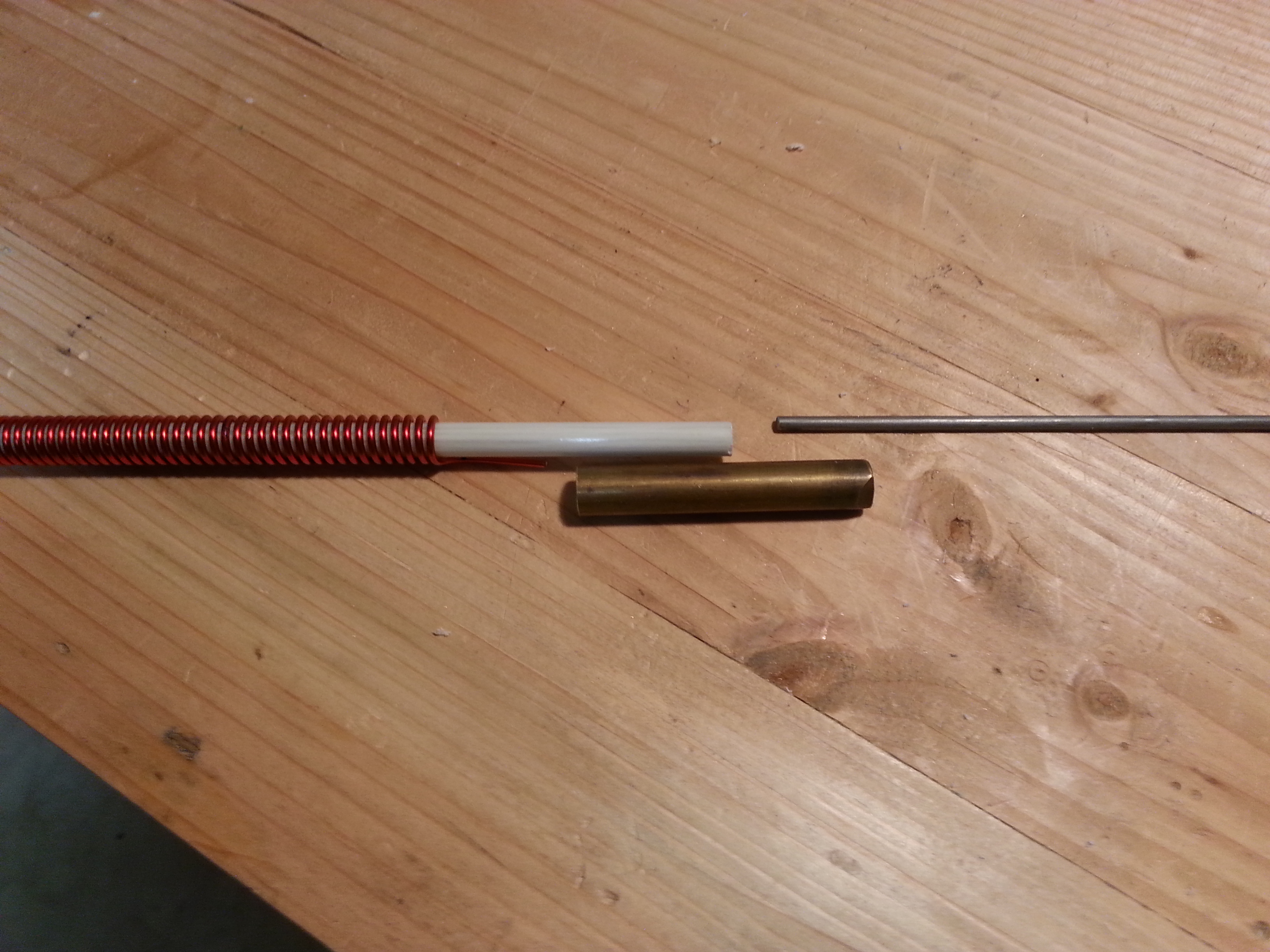
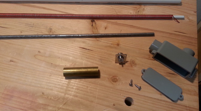
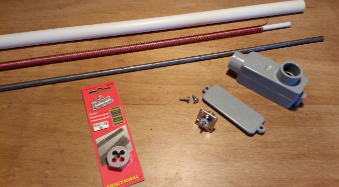
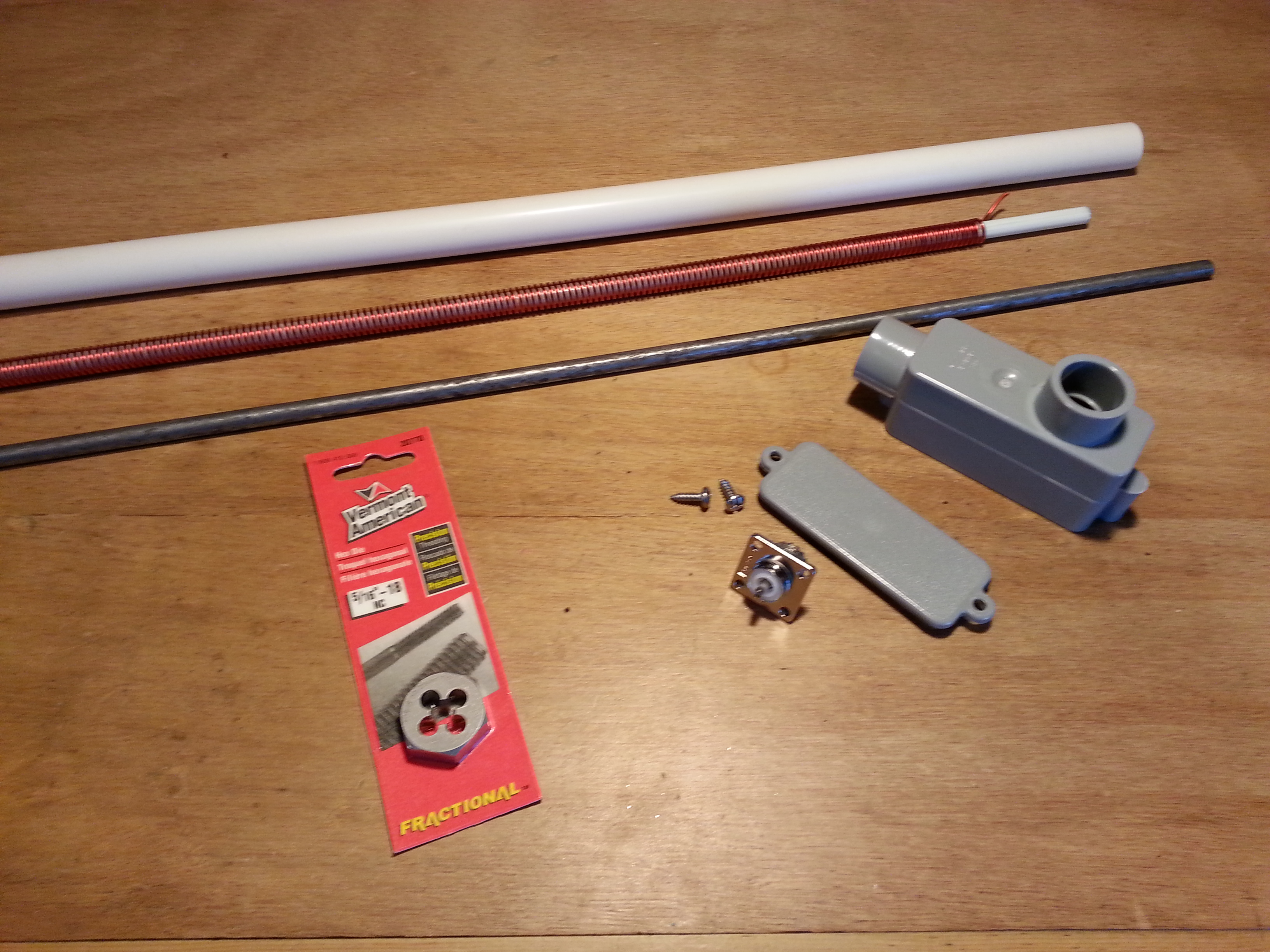
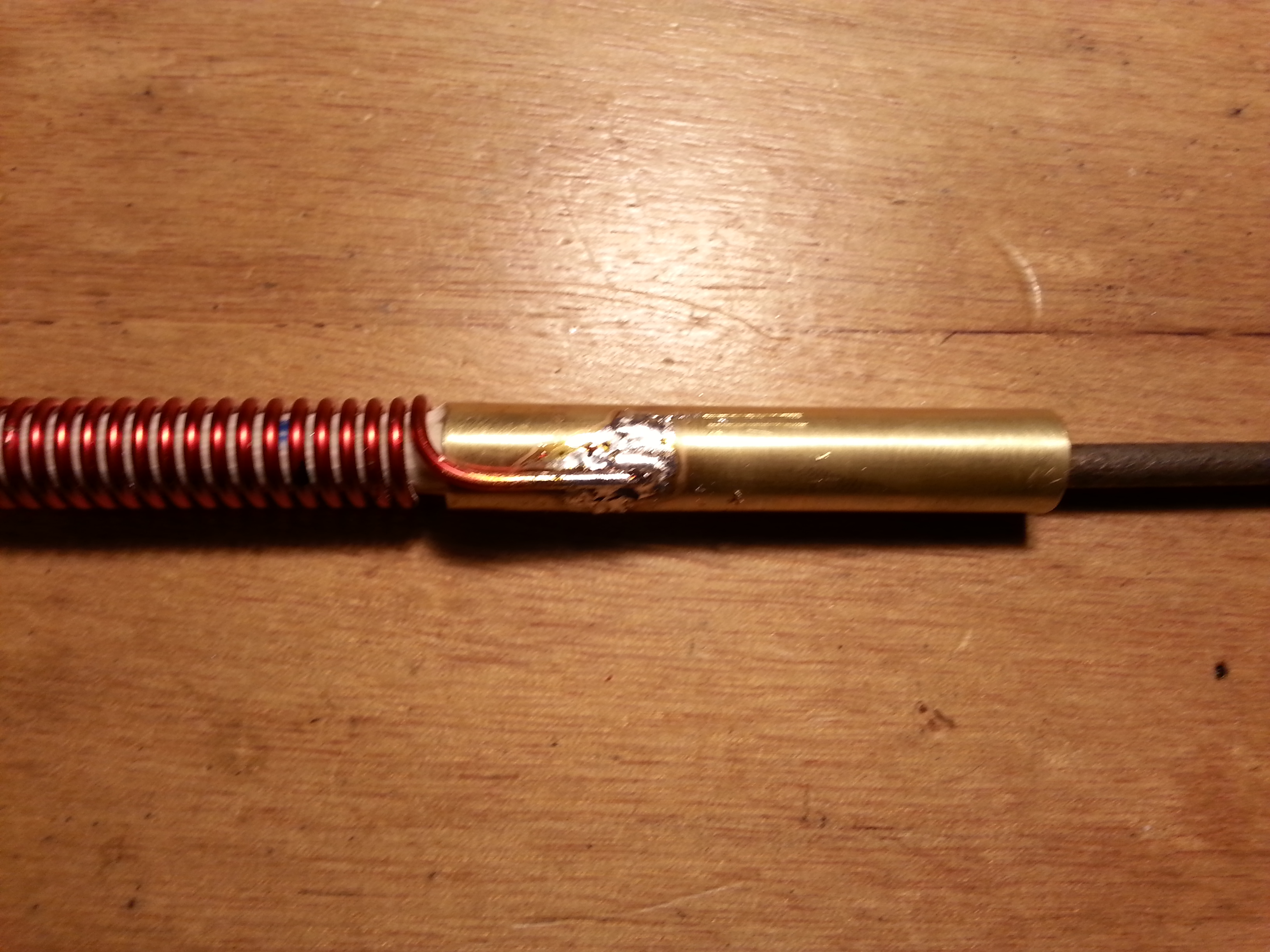
With this project I wanted to keep things as simple as possible and use off-the-shelf materials that are easily found and relatively cheap. One of the pieces I wanted was a simple piece of hardware I have seen many times. I have even bought it and used it, a three or four-inch long nut.  We used to use them for connecting CB antennas to rigid mounts with a nylon spacer block on the bottom and a bolt. The same basic format used to connect the spring mount base for mobile use. The intended use in this project is to connect the steel spike at the top of the antenna to the fiberglass body.

I remember buying these at Orchards Supply and Ace Hardware. I never had a problem finding one back in the 80s. Yesterday I went to OSH and Home Depot and the employees looked at me like I was from mars. They had these little 1-1.5 inch versions for connecting all-thread, which is what I am looking for, just longer. No clue. Nothing registered on their faces, even with the smaller version in my hand.

20150426_122018
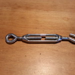
Anyway, the next closest thing was turnbuckle bodies. The “solid” bodies were aluminum and the open body type looked like nickel plate and galvanized. I ended up buying an open body style, but it really brought about several issues. First and foremost are the mechanical issues. The contact points on both ends are fairly small, less than half an inch. Even with the fiberglass rod and the steel spike screwed down all the way and touching there is still only a half inch of contact on either end.  These things are intended for stresses in tension not in bending which s what they will be exposed to in this application.

The next issue is the left-hand thread of one end of the turnbuckle. I was willing to deal with this I even started looking for a LH die to thread the fiberglass and this is where I decided to take a step back, reevaluate, and take stock of my options.

20150426_121813At this point the base end has been worked out. The right-angle conduit box is the base and will have 12 inches of half-inch PVC conduit inserted in the port that is parallel to the box. The wound fiberglass rod will be inserted through the PVC pipe into the base. I will cut off all but an eight-inch of the other port which will be the outside housing of the SO-239 which will be inserted from the inside of the box.

Once the antenna coil is soldered to the SO-239 on the inside of the box I will fill the box and the PVC pipe with polyester resin making the base a single solid weatherproof piece. The reason for the PVC pipe being 12 inches long  is to provide a solid place for mounting standoffs to be attached. All done with off the shelf hardware and materials with only one minor modification and no special tools.

Now back to the top end and mounting the steel spike to the fiberglass rod. The most direct method is using the all-thread nut I originally wanted to use. Since it is not available, and a sufficient replacement in size, complexity, and structural strength does not appear to be an off the shelf item, at least around here, I guess I need to make one.

I thought of welding nuts together and other welded configurations but they all require more work than what is really the simplest solution. Drill a piece of half-inch bar stock and tap it for 5/16″ 18 threads per inch. I already picked up the die, now I just need the tap and drill.

This solution does require a couple of tools, tap and die along with their respective handles, the right size drill (an F), and a little machining. This operation isn’t really a big deal. If you have a bench top drill press it will make things easier, but it can be done by hand with a bench vice.

The remaining decision is material for the threaded block. I know I have aluminum and I think I have both steel and brass that are the right size, or at least useable.  I am leaning towards the steel or brass. Aluminum and steel don’t play well together when there is the potential for moisture penetration between the surfaces making galvanic corrosion an issue as well as heat dissipation and mechanical contact issues.

More to come on this subject soon.

73,
~Jon KK6GXG

40 Meter Antenna

With the direct conversion receiver now working and tuned into the 40 meter band, it’s time to get to work on a better choice of antenna. The dipole would be great if it were in the proper environment, but this indoor, RF noisy environment is not conducive to picking up much.

Since tuning the receiver to the band I have been picking up both voice and cw transmissions but they are deep in the band noise. The other issue is portability. While the dipole can be pulled down and packed up for field use, it won’t work well in a mobile environment and would be a chore at home to pull down and put back up. So a whip makes the most sense for now. If the whip works at home I can wind up the dipole and keep it in the ready for field use.

Right now my focus is on getting the receiver, antenna, and any needed matching equipment in place. Once that is all together I can turn my attention to filters, amplifiers, and a transmitter.

Scan from the 1975 ARRL Handbook, page 606.

The antenna is a helically wound vertical that I mentioned in a previous post All Aboard the Project Train. I ordered a six foot fiberglass safety flag whip for the core and a fresh 1.5 pound spool of 14 AWG copper magnet wire to get the project going.

Yesterday I started the antenna construction by unrolling the 66.5 feet of copper wire and marking it every five feet, mostly so I didn’t lose my count. After dinner I started winding the coil onto the fiberglass in a tight coil. The picture in the header for this post is the fiberglass with about 30 feet wound on.

20150422_093128
66.5′ of 14 AWG copper wound onto a6′ x 3/8″ fiberglass rod

After winding the rest of the wire onto the fiberglass I threaded a dentists tool in between the wire wraps up the full length of the rod to create the uniform spacing for the coil.

On reflection at this point I think I might have opted for an 8 or 10 foot rod. For most applications it might be a better choice but neither would fit well indoors so 6 foot it is. I may build another antenna like this if it works well and try different lengths and diameters for different applications. A 10 foot whip would be better with a 1/2″ core and any longer would need 3/4″ or 1″ to remain stable unless it were placed inside a tube and filled with epoxy resin, another option. I haven’t tested any of these, I’m just spitballing with the structural integrity issue and weather resistance.

20150421_220832Now that the coil is done, the most difficult and time consuming part I think, it is time to move on to the spike and the base.

The plan for the spike is to pick up a small piece of 3/8″ copper tubing about 4″ long and use a coax crimping tool to mechanically center and attach a 1/4″ steel rod to about 2″ then sweat solder it together. After the spike is properly affixed, scoot the coil up a bit and solder the copper wire to the tube, add some epoxy inside the tube and scoot it back onto the fiberglass rod. This should give plenty of mechanical stability to both the spike and the rod as well as a good electrical contact. To help prevent galvanic corrosion I will coat the steel/copper interface with a few coats of lacquer.

The base is where I am going to have to think some more. The diagram calls for a variable inductor at the base of the antenna. I don’t think I will need this because I am planning on using an adapted Z-Match antenna tuning unit from chapter 23 of QRP Basics but that is for the next project.

OLYMPUS DIGITAL CAMERAIn the mean time I am thinking about using a PVC/ABS 90º conduit fitting with an access panel, cutting off and sealing up the right angle (on the bottom of the image), inserting the bottom of the antenna with the wire sticking up out of the box a little and filling the cavity with epoxy resin, leaving enough room to install an exterior lug fitting to attach the wire to on the inside.  For mechanical stability and to provide a secure mounting point I was thinking about using 6″ of conduit around the antenna and filling that with epoxy resin as well.

I hope to get the spike done this week and the base over the weekend. While out and about getting the final parts for the antenna I will be hitting HSC for the parts for the Z-Match. Another busy week for radio. 🙂

73,
~Jon KK6GXG